Download 2001-2005 KIA Optima Service Repair Manual –

online
Replacing the MacPherson strut on a Kia Optima involves several steps and requires specific tools and equipment. click here for more details on the download manual…..


    KIA OPTIMA FRONT WHEEL HUB BEARING ASSEMBLY REPLACEMENT REMOVAL KIA OPTIMA FRONT WHEEL HUB BEARING ASSEMBLY REPLACEMENT REMOVAL If you have Kia Optima and you need to …

    KIA OPTIMA VALVE COVER GASKET REPLACEMENT REMOVAL KIA OPTIMA VALVE COVER GASKET REPLACEMENT REMOVAL If you have Kia Optima and you need to replace valve cover …

below is a detailed guide outlining the process, the tools needed, and the safety precautions to take:

### Tools and Equipment Required:
– **Jack and Jack Stands**: Used to lift and secure the vehicle.
– **Lug Wrench**: To remove the wheel lug nuts.
– **Socket Set**: A comprehensive set including various sizes (usually metric) for removing bolts and nuts.
– **Torque Wrench**: To ensure bolts are tightened to manufacturer specifications.
– **Strut Spring Compressor**: This tool safely compresses the coil spring to allow for the removal and installation of the strut assembly.
– **Pry Bar**: Useful for separating components that may be stuck together.
– **Pneumatic or Electric Impact Wrench**: Optional, but can speed up the process of removing stubborn bolts.
– **Crescent Wrench or Adjustable Wrench**: For any additional adjustments needed.
– **Safety Glasses**: To protect your eyes while working.
– **Gloves**: To protect your hands and improve grip.
– **Shop Manual**: For torque specifications and specific vehicle instructions.

### Safety Precautions:
– Ensure the vehicle is on a flat surface and the parking brake is engaged.
– Always use jack stands after lifting the vehicle with a jack to prevent accidents.
– Wear safety gear to protect yourself from injuries.

### Procedure for MacPherson Strut Replacement:
– **Prepare the Vehicle**:
– Park the Kia Optima on a level surface and engage the parking brake.
– Loosen the lug nuts slightly while the vehicle is still on the ground.

– **Lift the Vehicle**:
– Use the jack to lift the front of the vehicle and secure it with jack stands.
– Remove the wheel by taking off the lug nuts completely.

– **Access the Strut Assembly**:
– Locate the strut assembly which is typically mounted to the steering knuckle and the strut tower.
– Remove any components blocking access to the strut (e.g., brake line brackets, ABS sensor wires).

– **Remove the Strut from the Steering Knuckle**:
– Use a socket and wrench to remove the bolts securing the strut to the steering knuckle.
– You may need to use a pry bar to gently separate the strut from the knuckle if it’s stuck.

– **Remove Strut Tower Bolts**:
– Open the hood to access the strut tower.
– Remove the bolts securing the top of the strut to the strut tower using the socket set.

– **Compress the Coil Spring**:
– Using a strut spring compressor, carefully compress the coil spring on the strut assembly. Follow the manufacturer’s instructions for the compressor to ensure safety.
– Once the spring is compressed, remove the top nut of the strut using a socket.

– **Remove the Strut Assembly**:
– With the spring compressed and the top nut removed, carefully remove the strut assembly from the vehicle.

– **Install the New Strut**:
– Position the new strut in place and secure it to the strut tower with the top bolts.
– Ensure the strut is correctly oriented (the top should match the original strut).

– **Recompress the Spring (if applicable)**:
– If the new strut requires the existing spring, place it on the new strutdownload KIA Optima workshop manual and carefully decompress it to allow the strut to seat properly.

– **Reattach to the Steering Knuckle**:
– Align the strut with the steering knuckle and secure it using the previously removed bolts. make sure to torque them to the manufacturer’s specifications.

– **Reassemble Other Components**:
– Reattach any brake line brackets, ABS sensors, or other components that were removed.
– Replace the wheel and hand-tighten the lug nuts.

– **Lower the Vehicle**:
– Carefully remove the jack stands and lower the vehicle back to the ground.

– **Final Tightening**:
– Once the vehicle is on the ground, use a torque wrench to tighten the lug nuts to the proper specification.

– **Test Drive**:
– Take the vehicle for a short test drive to ensure everything is functioning correctly and check for any unusual noises or handling issues.

### Conclusion:
This guide provides a comprehensive overview for replacing the MacPherson strut on a Kia Optima. Always refer to the vehicle’s service manual for specific torque specifications and procedures. If you are not comfortable performing this task, consider seeking help from a professional mechanic.
The water pump pulley is a crucial component in an Automotive cooling system, playing a vital role in maintaining optimal engine temperatures. Positioned on the front of the engine, it is typically attached to the water pump, which is responsible for circulating coolant throughout the engine block, radiator, and heater core. The main function of the water pump pulley is to transfer rotational energy from the engine’s crankshaft to the water pump itself, enabling it to operate effectively.

The pulley is usually made from durable materials such as aluminum or plastic, designed to withstand the high temperatures and pressures associated with engine operation. It is connected to the engine’s accessory drive belt system, which can include serpentine belts or V-belts. When the engine runs, the crankshaft turns, and this motion is transferred via the belt to the water pump pulley, causing the water pump to spin. This spinning action draws coolant from the radiator and pushes it through the engine, absorbing heat and preventing overheating.

Over time, the water pump pulley can experience wear and tear due to factors such as heat, vibration, and exposure to coolant. A failing pulley may lead to inefficient coolant circulation, resulting in engine overheating and potential damage. Regular inspection of the water pump pulley, along with the associated belts, is essential for maintaining the overall health of an engine’s cooling system.

Download 2015 Volkswagen Multivan T6 Download Service & Repair Manual –

purchase
Adjusting the suspension geometry on a Volkswagen Multivan T6 involves several components and settings that affect the vehicle’s handling, comfort, and tire wear. click here for more details on the download manual…..


    VW CAMPER GOT HIT [ Small Bodyline dent repair fixed! Small Bodyline Dents Look Bad! Volkswagen Transporter T6 door dent damage, repaired by Dent Remover in Hedon, East …

    What is The BEST OBD2 Diagnostic Scan Tool for T4 T5 T6 VW Transporter van or Campervan – ANSWERE… ANSWERED – This video will show you the best handheld VW Transporter T4 T5 T6 or campervan Scan Tools. VAWS V1.0 …

Proper suspension geometry ensures that the vehicle’s wheels are correctly aligned and positioned relative to the road and each other. Here’s a detailed guide on how to perform suspension geometry adjustment, including the necessary components and their functions.

### Key Components of Suspension Geometry

1. **Camber**:
– **Definition**: The angle of the wheels in relation to the vertical axis when viewed from the front of the vehicle.
– **Adjustment**: Often adjusted via the top mounting points of the strut or control arms.

2. **Caster**:
– **Definition**: The angle of the steering axis when viewed from the side of the vehicle. Positive caster helps with straight-line stability.
– **Adjustment**: Usually adjusted by modifying the position of the upper control arm or through specific adjustments on the strut mounts.

3. **Toe**:
– **Definition**: The angle of the wheels in relation to the centerline of the vehicle when viewed from above. Can be “toe-in” (wheels pointing slightly inward) or “toe-out”.
– **Adjustment**: Typically adjusted via tie rods.

4. **Ride Height**:
– **Definition**: The height of the vehicle’s body relative to the ground.
– **Adjustment**: Modified by changing the coil springs or adjusting the air suspension if equipped.

5. **Alignment Angles**: Ideally, all adjustments should be within the manufacturer’s specifications, which can often be found in the service manual or a dealership.

### tools and Equipment Needed

– **Alignment Machine or Alignment Tools**: For precise measurement of camber, caster, and toe.
– **Jack and Jack Stands**: To lift the vehicle safely for adjustments.
– **Wrenches and Sockets**: To adjust suspension components.
– **Torque Wrench**: To ensure all bolts are tightened to the manufacturer’s specifications.
– **Measuring Tape**: For measuring ride height and wheel positions.
– **Level**: To ensure the vehicle is on a flat surface during adjustments.

### Step-by-Step Adjustment Process

1. **Preparation**:
– Ensure the vehicle is on a flat surface.
– Remove any debris or obstructions from the wheels and undercarriage.
– Check tire pressures and adjust if necessary, as improper tire pressure can affect alignment settings.

2. **Lift the Vehicle**:
– Use a jack to lift the vehicle and secure it on jack stands. Ensure the vehicle is stable before beginning work.

3. **Inspect the Suspension Components**:
– Before making adjustments, visually inspect all suspension components for wear or damage. Pay particular attention to bushings, ball joints, and tie rods.

4. **Adjust Camber**:
– **Procedure**: Locate the upper strut mounts. Loosen the bolts holding the strut in place (do not remove). Adjust the strut position to achieve the desired camber angle. tighten the bolts to the specified torque.
– **Measurement**: Use the alignment machine to measure camber angle after adjustment.

5. **Adjust Caster**:
– **Procedure**: If necessary, adjust the upper control arm or strut mount. This may involve moving the upper control arm forward or backward to increase or decrease caster.
– **Measurement**: Again, use the alignment machine to check the caster angle.

6. **Adjust Toe**:
– **Procedure**: Locate the tie rods. To adjust toe-in or toe-out, turn the tie rod ends in or out. Make small adjustments, as toe settings can significantly affect download Volkswagen Multivan T6 workshop manualhandling.
– **Measurement**: Measure the distance between the front and back of the tires to confirm toe settings.

7. **Adjust Ride Height**:
– **Procedure**: For vehicles with coil springs, adjust the spring preload if adjustable. For air suspension, use the control system to set the desired height.
– **Measurement**: Measure ride height from the ground to the wheel arch.

8. **Final Check**:
– After all adjustments, lower the vehicle back to the ground. Recheck all alignments to ensure they remain within specifications.
– Test drive the vehicle to check for any handling issues.

9. **Documentation**:
– Record all adjustments made and any readings taken for future reference.

### Conclusion

Suspension geometry adjustment on a Volkswagen Multivan T6 requires careful attention to detail and precision. It’s essential to make sure that all adjustments are within the manufacturer’s specifications to ensure optimal handling, tire wear, and vehicle performance. If you are not comfortable performing these adjustments, it is advisable to consult a professional mechanic with experience in vehicle alignments.
A lug wrench, sometimes referred to as a tire iron, is an essential tool used for loosening and tightening the lug nuts that secure a car’s wheels to its hubs. Typically made from durable materials like steel, a lug wrench is designed to withstand significant torque and force during its operation. The tool usually features a long handle that provides the necessary leverage to apply sufficient force to loosen tightly secured lug nuts.

Lug wrenches come in various designs, with the most common being the “cross” or “X” shape, which has four arms that accommodate different lug nut sizes, allowing for versatility in use. Some lug wrenches are also telescopic, allowing users to extend the handle for added leverage, making it easier to remove stubborn lug nuts. Additionally, many vehicles come equipped with a compact, often L-shaped, lug wrench as part of the emergency tire-changing kit.

Using a lug wrench is a straightforward process: the user positions the wrench over the lug nut, applies pressure in the correct direction (usually counterclockwise to loosen), and uses the leverage provided by the wrench handle to either loosen or tighten the nut. Proper use of a lug wrench is critical during tire changes, ensuring that the wheels are securely fastened to the vehicle, which is vital for safety on the road.

Download VOLVO EW180E Service and Repair Manual –

do your own repairs
Repairing an automatic transmission, especially on a specialized machine like the Volvo EW180E, requires a good understanding of mechanical principles and some technical skills. click here for more details on the download manual…..


    Volvo Wheeled Excavators E-series – Operating instructions – Maximize your uptime – 9/10 Learn decisive maintenance and service informations that will secure maximum uptime for the Volvo wheeled excavator.

    koparka Volvo EC480El

However, I can provide a simplified overview of the process. Remember that working on an automatic transmission can be complex, and if you’re not comfortable doing this, it’s always best to consult a professional mechanic.

### Overview of Automatic Transmission Repair

**1. Safety First:**
– **Park the Machine:** Make sure the Volvo EW180E is parked on a level surface and turned off.
– **Disconnect the Battery:** To avoid any electrical issues, disconnect the battery.

**2. Gather Tools and Materials:**
– Basic hand tools (wrenches, sockets, screwdrivers)
– Transmission fluid
– Transmission filter (if applicable)
– Gasket sealant
– Drain pan for old fluid
– Rags for cleaning

**3. Identify the Problem:**
– Before starting any repair, it’s crucial to understand the issue. Common problems include slipping gears, delayed shifting, or strange noises. You may need to check the transmission fluid level and condition.

**4. Remove the Transmission:**
– **Access the Transmission:** Depending on the design, you may need to remove other components (like the skid plate or protective covers) to access the transmission.
– **Drain the Fluid:** Locate the transmission pan and remove the drain plug or pan bolts. Allow the fluid to fully drain into a pan.
– **Unbolt the Transmission:** Carefully unbolt the transmission from the engine. You may also need to disconnect linkages, electrical connectors, and any driveshaft connections.

**5. Disassemble the Transmission:**
– **Remove the Transmission Pan:** After draining, remove the transmission pan to access the internal components.
– **Inspect Internal Parts:** Look for damaged, worn, or broken parts like gears, clutches, or bands. Take pictures or notes as you disassemble, which will help during reassembly.

**6. Replace Worn Parts:**
– Replace any damaged components identified during inspection. This may include clutches, seals, or gaskets. Make sure you have the correct replacement parts for the Volvo EW180E.

**7. Reassemble the Transmission:**
– Carefully reassemble the transmission in the reverse order of disassembly. Make sure everything is aligned correctly and securely fastened.
– Replace the transmission pan and reattach the drain plug.

**8. Reinstall the Transmission:**
– Lift the transmission back into place and secure it to the engine.
– Reconnect any linkages, electrical connectors, and driveshaft connections.

**9. Fill with New Transmission Fluid:**
– Using a funnel, pour the recommended type of transmission fluid into the transmission through the dipstick tube. Refer to the owner’s manual for the correct typedownload VOLVO EW180E workshop manual and amount.

**10. Test the Machine:**
– Reconnect the battery and start the machine. Allow it to warm up and check for any leaks around the transmission.
– Test the transmission by shifting through the gears to ensure it operates smoothly.

**11. Final Checks:**
– After a short test drive, recheck the fluid level and top off if needed. Look for any signs of leaks or abnormal sounds.

### Conclusion

While this overview simplifies the process, automatic transmission repair can be intricate and often requires specialized knowledge. If you encounter any difficulties or if the problem persists after your repairs, it is advisable to seek help from a professional mechanic or a Volvo service center. they have the tools and experience to diagnose and fix more complicated issues.
A car key is a small yet crucial component of vehicle operation and security. Traditionally made of metal, the key typically has a unique shape that corresponds to the ignition system of a specific vehicle model. It functions primarily to start the engine, allowing the driver to access the vehicle’s power and operate it. However, its role has evolved significantly with advancements in automotive technology.

Modern car keys often incorporate electronic elements, transforming them into what are known as transponder keys or smart keys. Transponder keys contain a small microchip that communicates with the car’s immobilizer system, which is designed to prevent unauthorized access and theft. When the key is inserted into the ignition or brought near the vehicle, it sends a unique code to the car, allowing the engine to start only if the code matches. This added layer of security has significantly reduced vehicle theft rates.

Moreover, some vehicles now utilize keyless entry systems, where the key fob remains in the owner’s pocket or bag. The car detects the fob’s presence and allows the driver to unlock the doors and start the engine with just a push of a button. This convenience, paired with enhanced security features, reflects the ongoing evolution of car keys in the context of modern automotive design. Overall, while seemingly simple, the car key plays a vital role in both the functionality and security of vehicles today.

Download 2018 BMW X5 sDrive25d (F15) OEM Download Service & Repair Manual Software –

bookshop
Performing a CV joint replacement on a BMW X5 sDrive25d F15 (OEM) requires a good understanding of automotive repair and the proper tools. click here for more details on the download manual…..


    8HP50-0021-OEM Output Shaft Without Ring 4WD 8HP50 Automatic Transmission 8 SPEED For great wall Hello everybody. We are AATP Andy Auto Parts Team; we are mainly engaged in auto transmission parts, including …

    BMW X5 SDRIVE25D M SPORT AUTO SUV Engine Reconditioned | BM Engine Works Reviews Hi I am at BM Engine works Just had my X5 engine redone I am very happy with service They came and picked my car up off me It …

Please note that this is a general guideline and should be performed by a qualified technician or experienced DIYer. Below is a detailed outline of the necessary steps and tools involved in the process:

### Tools and Equipment Needed

– **Jack and Jack Stands**:
– A hydraulic jack to lift the vehicle and jack stands to support it securely while working underneath.

– **Socket Set**:
– A complete set of sockets (including metric sizes) for loosening and tightening bolts.

– **Wrench Set**:
– Open-end and box-end wrenches to fit various fasteners.

– **Torque Wrench**:
– To ensure that bolts are tightened to manufacturer specifications.

– **Pry Bar**:
– For leverage when removing parts.

– **Hammer**:
– To assist in loosening stubborn components.

– **CV Joint Puller or Slide Hammer**:
– To safely remove the CV joint from the axle shaft.

– **Pliers**:
– Needle-nose or locking pliers for removing clamps and clips.

– **Grease**:
– High-quality grease specifically designed for CV joints.

– **Replacement CV Joint Kit**:
– Includes new CV joint, boot, clamps, and grease.

– **Safety Gear**:
– Gloves, safety goggles, and steel-toed boots for personal protection.

### procedure for CV Joint Replacement

– **Preparation**:
– Park the vehicle on a flat surface and engage the parking brake.
– Place wheel chocks behind the rear wheels to prevent movement.

– **Lifting the Vehicle**:
– Use the hydraulic jack to lift the front end of the vehicle.
– Securely place jack stands under the vehicle’s frame.

– **Removing the Wheel**:
– Use a socket wrench to remove the lug nuts and take off the front wheel.

– **Accessing the CV Joint**:
– Remove any plastic covers or shields to access the axle area.
– Detach the brake caliper and rotor (if necessary) for better access. Ensure to suspend the caliper to avoid stress on the brake line.

– **Disconnecting the Axle**:
– Locate and remove the axle nut using a socket wrench (may require a breaker bar if it’s tightly torqued).
– If necessary, use a pry bar to gently separate the axle from the hub assembly.

– **Removing the CV Joint**:
– Depending on the design, you may need to remove additional components (like the control arm) to fully access the CV joint.
– Use a CV joint puller or slide hammer to detach the CV joint from the axle shaft. Be careful not to damage surrounding components.

– **Preparing the New CV Joint**:
– Open the replacement CV joint kit and apply the included grease to the new joint as per the manufacturer’s instructions.
– Install the new boot onto the CV joint, ensuring it is secured with the provided clamps.

– **Installing the New CV Joint**:
– Align the new CV joint with the axle shaft and gently tap it into place if necessary. Ensure it is seated correctly.
reinstall any components that were removed to access the CV joint, such as control arms.

– **Reassembling the Axle**:
– Position the axle back into the hubdownload BMW X5 sDrive25d F15 OEM workshop manual and secure it with the axle nut. Use a torque wrench to tighten to the specified torque settings.

– **Reinstalling the Wheel**:
– Place the wheel back onto the hub and hand-tighten the lug nuts.
– Lower the vehicle back to the ground and then use a torque wrench to tighten the lug nuts to the specified settings.

– **Final Checks**:
– Reattach any plastic covers or shields that were removed.
reinstall the brake caliper and rotor if removed.
– Perform a visual inspection to ensure all components are secure and properly installed.

– **Testing**:
– Once everything is reassembled, take the vehicle for a short test drive to ensure the CV joint is functioning properly and there are no unusual noises.

### Safety and Recommendations

– Always consult the vehicle’s service manual for specific torque specifications and detailed procedures.
– If unsure about any steps, it is advisable to seek professional assistance.
– Proper disposal of old parts and any hazardous materials should be done in accordance with local regulations.
The emergency brake, also known as the handbrake or parking brake, is a crucial safety feature in vehicles designed to secure the car in place when parked and to provide additional stopping power in case of a primary brake failure. Typically operated by a lever or pedal, the emergency brake engages the rear wheels of the vehicle, preventing it from rolling away on inclines or declines. In most modern vehicles, the emergency brake is a mechanical system that operates independently of the main hydraulic brake system, allowing it to function effectively even if the primary brakes fail.

The design and operation of emergency brakes can vary. In older models, the handbrake is often a lever located between the front seats, which the driver pulls upward to engage. In more recent vehicles, some have transitioned to electronic parking brakes, which use a button or switch to activate a motor that applies the brake. This shift has enabled features like auto-hold, which keeps the vehicle stationary on inclines without the driver needing to hold the brake pedal.

Using the emergency brake correctly is essential for vehicle safety. It is recommended to engage the emergency brake every time the car is parked, especially on inclines, to prevent unintentional movement. Additionally, regular maintenance checks are essential to ensure that the emergency brake is functioning correctly, as neglecting this component can lead to potentially dangerous situations.

Download Hyundai Wheel Loaders HL757-7 Service Manual –

australia
Replacing the lower control arm on a Hyundai HL757-7 wheel loader can seem daunting, especially if you have limited mechanical experience. click here for more details on the download manual…..


      Hyundai HL760-9 Wheel Loader

    However, with the right guidance and some patience, you can tackle this job. Here’s a step-by-step explanation of how to do it:

    ### Tools and Materials Needed:
    – Safety equipment (gloves, goggles, etc.)
    – Jack and jack stands
    wrenches and sockets (specific sizes will depend on your vehicle)
    – Torque wrench
    – Hammer
    – Pry bar
    – Replacement lower control arm
    – Lubricant (like grease)

    ### Steps for Lower Control Arm Replacement:

    1. **Safety First**:
    – Make sure the wheel loader is on a flat surface.
    – Engage the parking brake and turn off the engine.
    – Wear safety gloves and goggles for protection.

    2. **Lift the Wheel Loader**:
    – Use a jack to lift the front end of the wheel loader.
    – Place jack stands securely under the frame to support the vehicle. Never work under a vehicle supported only by a jack.

    3. **Remove the Wheel**:
    – Use a wrench or socket to loosen and remove the lug nuts on the wheel you’re working on.
    – Carefully take the wheel off and set it aside.

    4. **Locate the Lower Control Arm**:
    – The lower control arm is a metal arm that connects the frame of the wheel loader to the wheel hub. It helps with the wheel’s movement and stability.

    5. **Disconnect the Lower Control Arm**:
    – Look for bolts connecting the lower control arm to the frame and the wheel hub. Use the appropriate socket or wrench to remove these bolts.
    – If the bolts are tight, you may need to use a hammer to gently tap them out or apply some lubricant to help loosen them.

    6. **Remove the Old Control Arm**:
    – Once the bolts are removed, the lower control arm should come free. You may need to use a pry bar to help separate it from the vehicle if it’s stuck.

    7. **Install the New Control Arm**:
    – Take your new lower control arm and position it where the old one was removed.
    – Align it with the mounting points on the frame and the wheel hub.

    8. **Reconnect the Bolts**:
    – Insert and hand-tighten the bolts to hold the new control arm in place.
    – Once all bolts are in position, use your torque wrench to tighten them to the manufacturer’s specifications. this information can usually be found in the service manual.

    9. **Replace the Wheel**:
    – Reattach the wheel, making sure it is aligned properly.
    – Hand-tighten the lug nuts,download Hyundai Wheel Loaders HL757 7 workshop manual 
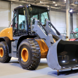
and then lower the wheel loader back to the ground before fully tightening the lug nuts in a crisscross pattern.

    10. **Final Checks**:
    – Ensure everything is securely fastened and that there are no leftover parts.
    – Check for any unusual sounds or movements when you first drive the wheel loader after the repair.

    ### Conclusion:
    Replacing a lower control arm can be challenging, but by following these steps carefully, you can complete the task with confidence. If you encounter any issues or feel unsure at any point, don’t hesitate to consult a more experienced mechanic or refer to the vehicle’s service manual for specific details related to your model. Always prioritize safety and double-check your work before putting the wheel loader back into operation.
    The oil drain gasket, also commonly referred to as the oil pan gasket, is an essential component of an internal combustion engine’s lubrication system. Its primary function is to create a seal between the oil pan and the engine block, preventing the engine oil from leaking out. this gasket is typically made from materials like rubber, silicone, or composite materials that can withstand the high temperatures and pressures found in an engine environment.

    The oil drain gasket plays a crucial role in maintaining the integrity of the engine’s lubrication system. A properly sealed oil pan ensures that the engine oil remains contained, allowing it to efficiently lubricate the moving parts of the engine, reduce friction, and dissipate heat. Over time, due to factors like age, heat cycling, and exposure to oil, the gasket can deteriorate, leading to leaks. An oil leak can result in a decrease in oil levels, which can cause engine wear, overheating, and potentially catastrophic engine failure if not addressed promptly.

    Replacing a worn or damaged oil drain gasket is a relatively straightforward maintenance task, yet it is vital for the overall health of the engine. Regular inspections and maintenance can help identify potential issues with the gasket, ensuring optimal engine performance and longevity. In summary, the oil drain gasket is a small but critical component that plays a vital role in the effective operation of an engine’s lubrication system.

    Download Mazda 323 1981-1989 Service Manual / Repair Manual –

    repair
    Differential service on a Mazda 323 involves inspecting, draining, and replacing the differential fluid to ensure optimal performance and longevity of the vehicle’s drivetrain. click here for more details on the download manual…..


      Mazda 323 1 3 – Front Wheel Bearings Bearings are essential to keep the wheels turning on any vehicle, see how to replace front wheel bearings on a Mazda 323 1.3 …

      Familia Fortunes: Mazda 1000 and 323 (BF) – A Real Road Test In this video, I drive two generations of Mazda Familia, on some of the most congested roads I’ve ever seen. Contains hot wiper …

    Here’s a detailed guide on how to perform this service, including descriptions of the tools needed:

    – **Tools Required**:
    – **Jack and Jack Stands**: To lift the vehicle safely and provide access to the differential.
    – **Description**: A hydraulic floor jack is recommended for lifting the vehicle, along with jack stands to securely support it once elevated. Ensure they are rated for the weight of your vehicle.

    – **Socket Set**: To remove the differential cover or drain plug.
    – **Description**: A metric socket set (typically 10mm to 14mm) is needed. A ratchet and extension may also be required for better reach and leverage.

    – **Torque Wrench**: To ensure bolts are tightened to manufacturer specifications.
    – **Description**: An adjustable torque wrench that covers the necessary torque range for the differential cover bolts.

    – **Fluid Pump or Syringe**: For adding new differential fluid.
    – **Description**: A fluid pump specifically designed for gear oil or a large syringe can help transfer the new fluid into the differential without spills.

    – **Drain Pan**: To catch old fluid while draining.
    – **Description**: A large, shallow pan that can hold several quarts of fluid to prevent mess during the draining process.

    – **Rags or Shop Towels**: For cleaning up spills and wiping tools.
    – **Description**: Absorbent towels that can easily clean up any fluid spills and keep your workspace tidy.

    – **New Differential Fluid**: To refill the differential.
    – **Description**: Consult the vehicle’s owner manual for the appropriate type and viscosity of differential fluid (often 75W-90 gear oil for a Mazda 323).

    – **Gasket or RTV Sealant**: If replacing the differential cover or needing to reseal it.
    – **Description**: A new gasket or high-temperature RTV sealant to ensure a proper seal after reassembly.

    – **Procedure**:
    – **Preparation**:
    – Park the vehicle on a level surface and engage the parking brake. Gather all tools and materials beforehand to streamline the process.

    – **Lifting the Vehicle**:
    – Use the jack to lift the rear of the vehicle, locating the jack points specified in the owner’s manual. Secure the vehicle with jack stands.

    – **Accessing the Differential**:
    – Locate the differential cover or drain plug. This is typically found on the rear axle assembly.

    – **Draining Old Fluid**:
    – Place the drain pan under the differential. If equipped with a drain plug, remove it using the appropriate socket. If not, you may need to remove the differential cover.
    – Allow the old fluid to completely drain out. This may take several minutes.

    – **Inspecting Components**:
    – While the fluid is draining, inspect the differential for any metal shavings or debris. This could indicate potential issues with the gears or bearings.

    – **Cleaning and Re-sealing**:
    – If the differential cover was removed, clean the mating surfaces with a scraper or Wire brush to remove old gasket material. Apply a new gasket or RTV sealant as required.

    – **Refilling with New Fluid**:
    – Replace the drain plug or reattach the differential cover, tightening the bolts to the specified torque.
    – Use the fluid pump or syringe to add new differential fluid through the fill hole until it reaches the proper level (usually until it begins to overflow slightly).

    – **Final Checks**:
    – Replace any fill plugs, ensuring they are secure. Check for leaks around the differential cover after servicing.

    – **Lower the Vehicle**:
    – Carefully remove the jack sdownload Mazda 323 workshop manualtands and lower the vehicle back to the ground using the jack.

    – **Test Drive**:
    – Take the vehicle for a short drive to ensure everything is functioning correctly and to check for any leaks.

    By following these steps and using the appropriate tools, you can successfully service the differential on a Mazda 323, helping to maintain the vehicle’s performance and reliability. Always refer to the vehicle’s service manual for specific details related to your model year.
    A parking sensor is an advanced automotive safety feature designed to assist drivers in parking their vehicles and avoiding obstacles. Typically installed in the front and/or rear bumpers of a car, parking sensors use ultrasonic or electromagnetic technology to detect objects in the vicinity of the vehicle. The primary function of these sensors is to provide real-time feedback to the driver about the distance between the car and any nearby obstacles, ensuring safer and more precise maneuvering in tight spaces.

    Ultrasonic parking sensors work by emitting sound waves that bounce off nearby objects. The system calculates the time it takes for the sound waves to return, determining the distance to the obstacle. Most systems are equipped with a series of sensors that cover a wide area, allowing for comprehensive detection of objects, including pedestrians, other vehicles, and stationary barriers. When an object is detected, the system alerts the driver through visual indicators on the dashboard or through audible beeps that increase in frequency as the vehicle approaches the obstacle.

    Parking sensors enhance safety, particularly in urban environments where space is limited. They are particularly beneficial for new drivers or those driving larger vehicles that may have blind spots. In recent years, many vehicles have integrated parking sensors with additional features, such as rearview cameras and automated parking systems, further enhancing the overall parking experience. As technology continues to evolve, parking sensors are becoming increasingly sophisticated, contributing to safer driving environments.

    Download 2014 Mercedes-Benz E-Class E400 Coupe (C207) OEM Service & Repair Manual Software –

    online
    Replacing the clutch slave cylinder on a Mercedes Benz E-Class E400 Coupe C207 requires careful attention to detail and proper tools. click here for more details on the download manual…..


      #camshafts mercdes benz E Coupe/C 207 OEM เราจะค่อยๆนำเสนอวิธีการดูแลรักษา ซ่อมแซมรถและเทคนิคต่างๆเรื่อยๆ ขอบพระคุณทุกท่านที่เข้าชมและให้โอกาสและกำลังใจครับผม …

      Mercedes 🔥EASY and 😈QUICK⚡️ center cap removal and tool DIY works on AMG! In this video Mike Icee will show how to remove replace and install the wheel center caps on a Mercedes W212 E350 e-class.

    Below are the steps outlined with detailed descriptions of the necessary tools and the replacement process:

    ### Tools Required:
    – **Socket Set**: A complete set of metric sockets (including 10mm, 13mm, and 17mm sizes) to remove bolts and nuts.
    – **Ratchet Wrench**: A ratchet wrench to use with the socket set for faster removal and installation.
    – **Torque Wrench**: To ensure that bolts are tightened to the manufacturer’s specifications.
    – **Pliers**: For removing clips or hoses.
    – **Screwdrivers**: Flathead and Phillips screwdrivers for prying and securing components.
    – **Brake Cleaner**: To clean any spilled fluid and ensure a clean working area.
    – **Rags or Shop Towels**: For wiping hands and cleaning up any spills.
    – **Fluid Collection Pan**: To catch any leaking hydraulic fluid during the process.
    – **Replacement Clutch Slave Cylinder**: Ensure you have an OEM part for compatibility.
    – **New Hose Clamps**: If applicable, replace any old clamps for a secure fit.
    – **Jack and Jack Stands**: To safely lift the vehicle for access to the undercarriage.
    – **Wheel Chocks**: To prevent the vehicle from rolling while it’s on jack stands.

    ### Replacement Process:
    – **Prepare the Vehicle**:
    – Ensure the vehicle is parked on a flat surface.
    – Engage the parking brake to prevent movement.
    – Disconnect the negative terminal of the battery to avoid electrical issues during the replacement.

    – **Lift the Vehicle**:
    – Use a jack to lift the front of the vehicle.
    – Secure it with jack stands to provide a stable working environment.

    – **Remove the Underbody Covers** (if applicable):
    – Check for any plastic covers that may obstruct access to the transmission area.
    – Use a socket or screwdriver to remove any screws or clips securing the covers.

    – **Locate the Clutch Slave Cylinder**:
    – The clutch slave cylinder is typically located on the transmission housing.
    – Identify the hydraulic line leading to the cylinder for easier removal.

    – **Drain the Hydraulic Fluid**:
    – Place a fluid collection pan under the transmission.
    – Disconnect the hydraulic line from the slave cylinder carefully to allow fluid to drain into the pan.

    – **Remove the Old Clutch Slave Cylinder**:
    – Use the appropriate socket and ratchet to remove the mounting bolts securing the slave cylinder to the transmission.
    – Gently wiggle the cylinder to break it free from any seals and pull it out of the transmission.

    – **Prepare the New Clutch Slave Cylinder**:
    – Compare the new slave cylinder with the old one to ensure proper fitment.
    – Apply a small amount of hydraulic fluid to the O-rings of the new slave cylinder to aid installation.

    – **Install the New Clutch Slave Cylinder**:
    – Position the new slave cylinder into the mounting location on the transmission.
    – Align the bolt holes and secure it with the mounting bolts. Use a torque wrench to tighten the bolts to the manufacturer’s specifications.

    – **Reconnect the Hydraulic Line**:
    – Attach the hydraulic line to the new slave cylinder, ensuring a snug fit.
    – Use new hose clamps if needed to secure the line properly.

    – **Bleed the Clutch System**:
    – To remove any air from the hydraulic system, you will need to bleed the clutch.
    – Locate the bleeder valve on the slave cylinder.
    – Use a wrench to open the bleeder valve while someone presses the clutch pedal. close the valve before the pedal is released to avoid sucking air back in.
    – Repeat the process until no air bubbles appear in the fluid.

    – **Reinstall Underbody Covers** (if removed):
    – Replace any underbody covers that were removed during the process.
    – Secure them with the appropriate screws or clips.

    – **Lower the Vehicle**:
    – Carefully remove the jack sdownload Mercedes Benz E Class E400 Coupe C207 OEM workshop manualtands and lower the vehicle back to the ground.

    – **Reconnect the Battery**:
    – Reconnect the negative terminal of the battery.

    – **Test the Clutch**:
    – Start the vehicle and test the clutch operation to ensure everything is functioning correctly.
    – Check for any leaks around the slave cylinder and connections.

    ### Final Check:
    – After a short test drive, recheck for leaks and ensure proper engagement of the clutch. If any issues arise, revisit the installation steps to ensure all connections are secure.

    This detailed guide should help you successfully replace the clutch slave cylinder in your Mercedes Benz E-Class E400 Coupe C207. Always refer to your vehicle’s service manual for specific torque specifications and detailed information.
    The brake pedal switch, commonly referred to as the brake light switch, is a crucial component in a vehicle’s braking system. Located near the brake pedal, it is typically a small, electrical switch that is activated when the brake pedal is pressed down. This switch serves multiple essential functions that contribute to both vehicle safety and functionality.

    When the driver presses the brake pedal, the brake pedal switch closes its circuit, sending an electrical signal to activate the brake lights on the rear of the vehicle. This alerts other drivers that the vehicle is slowing down or stopping, significantly enhancing road safety by preventing rear-end collisions. In addition to controlling the brake lights, the brake pedal switch is also integral to the operation of various safety features within the vehicle. For instance, many cars use the brake switch to disengage the cruise control system when the brake is applied, ensuring that the vehicle decelerates when necessary.

    Furthermore, the brake pedal switch can be involved in triggering other systems, such as the anti-lock braking system (ABS) or electronic stability control (ESC). A malfunctioning brake pedal switch can lead to issues, such as brake lights remaining on or not illuminating at all, which can pose a safety hazard. Regular inspection and maintenance of the brake pedal switch are essential to ensure the proper functioning of the vehicle’s braking and safety systems.

    Download 2001 Chevrolet Silverado 3500 Service & Repair Manual Software –

    do your own repairs
    Suspension repair on a Chevrolet Silverado 3500 involves several components and procedures, depending on what specifically needs to be repaired or replaced. click here for more details on the download manual…..


      2500 vs 3500 Trucks – What's Really the Difference? We Compare Two Chevy Silverado HDs to Fin… We dig into the true differences between a Chevy Silverado 2500 and 3500. Are they mechanically different? Or is it just in the …

      BEST Chevy Intake Gaskets! BEST Chevy intake gaskets. Chevy engineers updated intake gasket design. Chevy Silverado intake gasket replacement. How to …

    Here’s a detailed guide to help you understand the process, along with descriptions of the components involved.

    ### Components of the Suspension System

    1. **Shock Absorbers/Struts**: These are hydraulic devices that absorb shocks from the road, helping to maintain tire contact with the road surface.

    2. **Coil Springs/Leaf Springs**: These provide support and absorb road shocks. The Silverado 3500 typically uses leaf springs in the rear and coil springs in the front.

    3. **Control Arms**: These connect the suspension system to the vehicle’s frame and allow for up-and-down movement of the wheels.

    4. **Ball Joints**: These connect the control arms to the steering knuckles and allow for smooth movement.

    5. **Sway Bar (Anti-Roll Bar)**: This helps reduce body roll during cornering by connecting the left and right wheels.

    6. **Bushings**: These are rubber or polyurethane components that cushion and support the control arms and other suspension components.

    7. **Alignment Components**: Includes camber, caster, and toe adjustments that help maintain proper wheel alignment.

    ### Tools Required

    – Jack and jack stands
    – Wrenches and sockets (metric and standard)
    – Torque wrench
    – Screwdrivers
    – Pry bar
    – Pliers
    – Hammer
    – Spring compressor (if replacing coil springs)
    – Suspension grease
    replacement parts (shocks, springs, control arms, etc.)

    ### Step-by-Step Suspension Repair Process

    #### 1. Safety First

    – Park the vehicle on a flat surface.
    – Engage the parking brake and wear safety goggles and gloves.

    #### 2. Lift the Vehicle

    – Use a jack to lift the front or rear of the vehicle, depending on which suspension components you are working on.
    – Secure the vehicle with jack stands to ensure it is stable.

    #### 3. Remove the Wheel

    – Use a lug wrench to remove the lug nuts and take off the wheel. This will give you access to the suspension components.

    #### 4. inspect the Suspension Components

    – Check for visible damage, such as leaks in the shocks, cracked or broken springs, worn bushings, or damaged control arms.
    – Replace any worn or damaged components as necessary.

    #### 5. Replacing Shock Absorbers

    – **Remove the old shock**: Unscrew the upper mounting bolts and lower bolts using the appropriate wrenches. You may need to hold the shaft with a wrench to prevent it from spinning.
    – **Install the new shock**: Position the new shock absorber in place and torque the bolts to the manufacturer’s specifications.

    #### 6. Replacing Springs

    – **Remove the coil spring (front)**:
    – **Coil springs**: If replacing front coil springs, use a spring compressor to safely compress the spring before removing it from the strut assembly.
    – Unbolt the strut assembly from the upper mount and lower control arm. Once removed, carefully release the spring tension.

    – **Install the new coil spring**: Place the new spring onto the strut and use the spring compressor to reassemble the strut. Ensure the spring is seated properly.

    – **Leaf springs (rear)**: If replacing rear leaf springs, unbolt the u-bolts holding the leaf spring to the axledownload Chevrolet Silverado 3500 workshop manual and the bolts connecting it to the frame. Install the new leaf spring and torque the bolts to specifications.

    #### 7. Replace Control Arms and Ball Joints

    – **Remove control arms**: loosen and remove the bolts connecting the control arms to the frame and steering knuckles. You may need to separate the ball joint from the steering knuckle using a ball joint separator tool.
    – **Install new control arms**: Position the new control arms and torque the bolts to specifications.

    #### 8. Replace Bushings

    – If you are replacing bushings in control arms or sway bars, press out the old bushings using a bushing removal tool or a press and install the new ones.

    #### 9. Reassemble Components

    – Reinstall any components you removed (like the sway bar) and torque bolts to the manufacturer’s specifications.
    – Reattach the wheels and torque the lug nuts in a star pattern.

    #### 10. Lower the Vehicle and Perform Alignment

    – Carefully lower the vehicle back to the ground.
    – After replacing suspension components, it’s essential to have a wheel alignment performed to ensure proper handling and tire wear.

    ### Final Checks

    inspect the suspension after installation to ensure everything is properly secured.
    – Take the vehicle for a test drive to check for any unusual noises or handling issues.

    ### Conclusion

    Suspension repair on a Chevrolet Silverado 3500 requires attention to detail and proper tools. Always refer to the vehicle’s service manual for specific torque specifications and procedures. If you are unsure about any step, consider consulting a professional mechanic to ensure the safety and performance of your vehicle.
    The side mirror, also known as the wing mirror or door mirror, is a crucial component of a vehicle that enhances safety and visibility. Located on the exterior of a car, typically mounted on the driver’s and passenger’s side, side mirrors provide drivers with a wider field of vision, allowing them to monitor adjacent lanes, check for blind spots, and gauge the distance of vehicles and obstacles around them.

    Modern side mirrors often come equipped with several advanced features. For instance, many models include integrated turn signal indicators, which enhance visibility for other drivers when changing lanes or turning. Additionally, some side mirrors have blind-spot monitoring systems that use sensors to alert drivers to vehicles lurking in their blind spots. Heated mirrors are also common in colder climates, preventing frost and ice accumulation that can obstruct visibility.

    In terms of design, side mirrors are aerodynamically shaped to minimize wind resistance and reduce noise while driving. They are typically adjustable, either manually or electronically, allowing drivers to customize their viewing angles for optimal visibility. Side mirrors can also be retractable, folding inwards to prevent damage in tight spaces, such as parking lots.

    Overall, the side mirror is an essential feature that enhances driving safety by providing critical visibility, facilitating safer lane changes, and reducing the risk of accidents. Its evolution reflects advancements in automotive technology, contributing to a more secure driving experience.

    Download Case 3, 445, 445CT Parts-

    workshop manual
    Replacing the valve body on a Case 3 445 or 445CT involves several steps. click here for more details on the download manual…..


      2010 CASE 445-3 For Sale http://www.MachineryTrader.com/listingsdetail/detail.aspx?OHID=9435997&lp=MAT Title: 2010 CASE 445-3 For Sale Description: …

      Parking brake release solenoid

    Here’s a reverse order outline of how to perform this task:

    ### 7. Reassemble the Equipment
    – **Reconnect any hoses or wiring** that were disconnected during the removal process.
    – **Reattach any covers or shields** that were removed to access the valve body.

    ### 6. Install the New Valve Body
    – **Carefully position the new valve body** in place, ensuring that all alignment pins and dowels are properly seated.
    – **Torque the bolts** to the manufacturer’s specifications, following the correct sequence to ensure even pressure distribution.

    ### 5. Clean and Prepare the Mounting Surface
    – **Clean the mounting surface** on the transmission housing where the valve body will sit. Remove any old gasket material or debris to ensure a good seal.
    – **Inspect the new valve body** for any shipping damage or defects before installation.

    ### 4. Remove the Old Valve Body
    – **Unbolt the valve body** from the transmission, taking care to note the order and position of the bolts.
    – **Gently lift out the old valve body**, taking care not to let any debris fall into the transmission during removal.

    ### 3. Drain the Transmission Fluid
    – **Locate the drain plug** on the transmission and drain the fluid into a suitable container. This will prevent spills and make the process cleaner.

    ### 2. Prepare the Work Area
    – **Gather all necessary tools and materials**, including a new valve body, gaskets, torque wrench, socket set, and any other required tools.
    – **Ensure the equipment is on a flat surface** and secured to prevent any movement during the replacement.

    ### 1. Safety First
    – **Disconnect the battery** to prevent any electrical issues while working on the hydraulic system.
    – **Wear appropriate safety gear**, including gloves and safety glasses, to protect yourself during the procedure.

    This reverse order outlines the steps you would take to replace the valve body on a Case 3 445 or 445CT. always refer to the specific service manual for detailed instructionsdownload Case 3 445 445CT Parts workshop manual and torque specifications for your particular model.
    A spark plug boot is an essential component of an internal combustion engine’s ignition system, playing a crucial role in the performance and efficiency of the engine. It is essentially the rubber or silicone covering that encases the end of the spark plug wire, which connects the ignition coil to the spark plug itself. The primary function of the spark plug boot is to ensure a secure electrical connection while protecting the wire from environmental factors such as heat, moisture, and contaminants.

    Spark plug boots are designed to withstand extreme temperatures, as they are located in close proximity to the engine and subjected to significant thermal stress. They often feature a high-temperature resistant material that prevents deterioration over time, which is vital for maintaining the integrity of the ignition system. A well-functioning spark plug boot helps to ensure that the electrical current can travel efficiently from the ignition coil to the spark plug, igniting the air-fuel mixture in the combustion chamber.

    Additionally, spark plug boots are designed with a specific shape and size to ensure a snug fit on both the spark plug and the ignition wire, minimizing the risk of misfiring or electrical leakage. Over time, these boots can wear out or become damaged, leading to issues such as poor engine performance, increased emissions, and difficulty starting the vehicle. Regular inspection and replacement of worn spark plug boots can contribute to the overall health of the engine, ensuring optimal ignition and fuel efficiency.

    Download 2007 BMW 545i (E60) 5 Series OEM Download Service & Repair Manual Software –

    service
    Replacing the struts on a BMW 545i E60 can seem daunting, especially if you have little mechanical experience. click here for more details on the download manual…..


      BMW 545i stock exhaust This is before exhaust mods.

      2004 BMW 545i pass rear seats Car for sale.

    However, with the right tools, patience, and careful steps, you can accomplish this task. Here’s a simplified guide to help you through the process.

    ### Tools and materials Needed:
    – **Tools:**
    – Socket set (with ratchet and extensions)
    – Wrench set
    torque wrench
    – Strut spring compressor (essential for handling the spring safely)
    – Jack and jack stands
    – Screwdrivers
    – Pliers
    – Hammer (optional)

    – **Materials:**
    – New struts (make sure they are compatible with the BMW 545i E60)
    – New strut mounts (recommended)
    – New strut boots (if necessary)
    – New bump stops (if necessary)
    – Lubrication (like grease) for the mounts

    ### Safety Precautions:
    1. **Work on a flat surface:** Make sure your car is parked on a level surface to prevent it from rolling.
    2. **Use jack stands:** Never rely solely on a jack; always use jack stands for safety.
    3. **Wear safety glasses and gloves:** Protect your eyes and hands from debris and sharp objects.

    ### Step-by-Step Guide:

    #### Step 1: Prepare the Vehicle
    1. **Loosen the lug nuts:** Before lifting the car, slightly loosen the lug nuts on the front wheels using a lug wrench. Don’t remove them yet.
    2. **Lift the car:** Use a jack to lift the front of the car and then place it securely on jack stands. Ensure the vehicle is stable before proceeding.

    #### Step 2: Remove the Wheels
    1. **Remove the lug nuts:** Now you can fully remove the lug nuts and take off the front wheels. Set them aside in a safe place.

    #### Step 3: Access the Strut Assembly
    1. **Locate the strut assembly:** The strut is the large cylindrical component connected to the wheel hub and the vehicle chassis.
    2. **Disconnect any components:** You may need to disconnect the brake line bracket, sensors, or other components that are attached to the strut. Be gentle to avoid damaging any wiring.

    #### Step 4: Remove the Strut
    1. **Remove the strut nuts on top:** Open the hood and locate the strut tower. You should see three nuts holding the top of the strut in place. Use a socket wrench to remove these nuts.
    2. **Support the strut:** Use a jack or a piece of wood to support the bottom of the strut as you remove it.
    3. **Remove the lower strut bolts:** At the bottom of the strut, there are usually two bolts connecting the strut to the wheel hub. Use a socket wrench to remove these bolts and gently pull the strut out.

    #### Step 5: Replace the Strut
    1. **Compress the spring:** If you are reusing the old spring, use a strut spring compressor to Safely compress the spring before removing it from the old strut. This is crucial for safety.
    2. **Install the spring on the new strut:** Once the spring is compressed, carefully install it onto the new strut, following the manufacturer’s instructions.
    3. **Reassemble the strut:** If you have new mounts or bump stops, install them on the new strut as well.

    #### Step 6: Install the New Strut
    1. **Position the new strut:** Carefully lift the new strut into place, aligning it with the bottom mount on the wheel hub.
    2. **Secure the lower bolts:** Insertdownload BMW 545i E60 5 OEM workshop manual and tighten the lower bolts first.
    3. **Secure the top of the strut:** Go back to the engine bay and secure the top of the strut by tightening the three nuts.

    #### Step 7: Reassemble Everything
    1. **Reconnect any components:** Reattach the brake line bracket, sensors, or any other components you disconnected earlier.
    2. **Reinstall the wheel:** Put the wheel back on and hand-tighten the lug nuts.

    #### Step 8: Lower the Car
    1. **Remove the jack stands:** Carefully lower the car back to the ground using the jack.
    2. **Tighten the lug nuts:** Once the car is on the ground, use a torque wrench to tighten the lug nuts to the manufacturer’s recommended torque specification.

    #### Step 9: Test Drive
    1. **Check for any issues:** Before taking a longer drive, do a short test drive to ensure everything feels right and there are no unusual noises.

    ### Final Thoughts
    Strut replacement can be a challenging task, but by following these steps carefully, you can successfully complete it. If at any point you feel uncomfortable or unsure, don’t hesitate to consult a professional mechanic. Enjoy your newly improved ride!
    A battery insulator is a crucial component in automotive and various electronic applications that serves multiple important functions related to the battery. Typically made from materials with excellent insulating properties, such as rubber, plastic, or specialized composites, a battery insulator is designed to prevent short circuits by providing a barrier between the battery terminals and other conductive surfaces. This is particularly vital in vehicles where vibrations and movements can cause components to shift, potentially leading to unintended contact and electrical failures.

    In addition to preventing electrical shorts, battery insulators also play a role in protecting the battery from environmental factors such as moisture, dirt, and thermal fluctuations. Many insulators are designed to be weather-resistant, ensuring that the battery remains operational in various conditions, from extreme heat to freezing cold. This protection helps extend the battery’s lifespan and maintain its performance.

    Moreover, battery insulators can contribute to the overall safety of the vehicle. By containing any potential leaks from the battery, they help minimize the risk of hazardous spills that could occur in the event of an accident or battery failure. Some insulators are also designed to dampen vibrations, which can further protect the battery and enhance durability.

    In summary, battery insulators are vital for ensuring the safety, efficiency, and longevity of batteries in vehicles and other electronic systems, making them a key component in modern automotive engineering.