Download Perkins 102-05 Diesel Engine Factory Service & Work Shop Manual –

bookstore
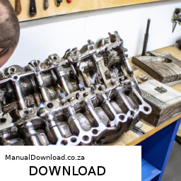
Lowering the control arm on a Perkins 102-05 engine can be a complex task, especially for someone without much mechanical experience. click here for more details on the download manual…..


      Here's Why the 5.9L Cummins is one of the Best Diesel Engines Ever Check out our website: dustrunnersauto.com Follow me on Instagram: @bryce.cleveland Gear I use to shoot my videos: (Buying …

    However, I’ll break it down into simple steps to make it easier to understand.

    **Important Note:** If you’re not comfortable doing this work yourself, it’s always best to consult with a professional mechanic. Safety should always come first.

    ### Tools and Materials Needed:
    1. **Basic Hand Tools:** Wrenches, sockets, and ratchet.
    2. **Jack and Jack Stands:** To lift the vehicle safely.
    3. **Pliers:** For any clips or fasteners.
    4. **Torque Wrench:** To ensure bolts are tightened to specifications.
    5. **Replacement Control Arm:** Ensure you have the correct part for your model.
    6. **Safety Gear:** Gloves and safety glasses.

    ### Steps to Lower the Control Arm:

    1. **Preparation:**
    – **Safety First:** Make sure you’re wearing gloves and safety glasses.
    – **Check the Environment:** Ensure you’re in a well-ventilated area and that the vehicle is on a flat, stable surface.
    – **Disconnect the Battery:** To prevent any electrical issues.

    2. **Lift the Vehicle:**
    – Use a jack to lift the vehicle from its designated lift points.
    – Once lifted, place jack stands securely under the vehicle to ensure it won’t fall while you work.

    3. **Remove the Wheel:**
    – Using a wrench or socket, loosen and remove the lug nuts on the wheel that is connected to the control arm you want to replace.
    – Take off the wheel and set it aside.

    4. **Locate the Control Arm:**
    – The control arm is usually a metal arm that connects the vehicle’s chassis to the wheel assembly. It may have bushings and ball joints attached to it.

    5. **Disconnect the Control Arm:**
    – Look for bolts that connect the control arm to the chassis and the wheel assembly.
    – Using the appropriate socket or wrench, carefully remove these bolts. Keep track of where they belong (you might want to label them or take a picture).

    6. **Remove the Control Arm:**
    – Once all bolts are removed, the control arm should be loose. You may need to wiggle it a bit to get it out. Be careful not to damage surrounding components.

    7. **Install the New Control Arm:**
    – Take your new control arm and align it where the old one was.
    – Insert the bolts back into the appropriate holes and hand-tighten them first to ensure everything is aligned properly.

    8. **Tighten the Bolts:**
    – Once the control arm is in place, use a torque wrench to tighten all bolts to the manufacturer’s specifications. This step is crucial for safety and proper vehicle handling.

    9. **Reattach the Wheel:**
    – Place the wheel back onto the hubdownload Perkins 102 05 Engine Work Shop workshop manual and hand-tighten the lug nuts.
    – Once the wheel is on, lower the vehicle slightly to the ground so you can fully tighten the lug nuts in a crisscross pattern for even tightening.

    10. **Lower the Vehicle:**
    – Remove the jack stands and then lower the vehicle completely to the ground.

    11. **Reconnect the Battery:**
    – Reconnect the battery terminal that you had disconnected earlier.

    12. **Test Drive:**
    – Take the vehicle for a short test drive to ensure everything feels right. Listen for any unusual noises or handling issues.

    ### Final Thoughts:
    Replacing a control arm can be a rewarding project, but it requires careful attention to detail and safety. If you encounter any difficulties, don’t hesitate to consult a professional mechanic.
    A lug wrench, also known as a tire iron or wheel brace, is a crucial automotive tool designed for loosening and tightening the lug nuts that secure a vehicle’s wheel to its hub. Typically made of steel, it features a long handle for leverage and a socket at one or both ends that fits the specific size of the lug nuts. The design of a lug wrench can vary, with some featuring a cross or star shape that allows for multiple nut sizes to be accommodated, while others may be a simple L-shape or a telescoping design that enhances portability and ease of use.

    The primary use of a lug wrench is during tire changes, whether due to a flat tire or routine maintenance such as rotating tires. When a driver encounters a flat tire, the lug wrench is an essential tool for removing the wheel. Its long handle provides the leverage necessary to break the torque applied to the lug nuts, which can be particularly tight due to the vehicle’s weight or rust accumulation.

    In addition to its practical use, lug wrenches are often included in a vehicle’s emergency kit, ensuring that drivers are prepared for unexpected tire issues. Some modern vehicles come equipped with specialized lug wrenches that may also incorporate features like built-in ratchets or extensions for added convenience. Overall, the lug wrench is a simple yet indispensable tool for any vehicle owner, emphasizing the importance of being prepared for roadside emergencies.

    Download Fiat Scudo 2.0 HDi Engine types RHX 2004 Service Repair Manual –

    online
    Repairing the shift detent on a Fiat Scudo 2.0 HDi (engine type RHX) involves several steps. click here for more details on the download manual…..


      Peugeot/Citroen 2.0 HDI Timing Marks / Timing Belt Replacement Peugeot/Citroen 2.0 HDI Timing Marks / Timing Belt Replacement #Peugeot #Citroen #20HDITiming.

      Ford Peugeot Citroёn Mazda Volvo Engine 1.6 HDI DV6C DV6D Timing Belt Replacement Manufacturer’s website www.ntn-snr.com Ford Peugeot Citroёn Mazda Volvo Engine 1.6 HDI DV6C DV6D Timing Belt …

    Here’s a reverse order explanation of the process:

    ### 7. Reassemble the Gear shift Assembly
    – Reinstall any covers or panels that were removed to access the shift detent.
    – Ensure all screws and bolts are tightened to the manufacturer’s specifications.

    ### 6. Test the shift Mechanism
    – Start the engine and test the Gear shift to ensure smooth operation.
    – Engage all gears to make sure that the detent is functioning correctly.

    ### 5. Reinstall the shift Detent and Spring
    – Carefully place the new or repaired detent and spring back into their designated positions within the gearbox.
    – Ensure that the detent is seated properly and that the spring is installed correctly to provide the necessary tension.

    ### 4. Access the Gearbox
    – Remove any necessary components such as the Gear shift lever or console to gain access to the gearbox.
    – Depending on the vehicle configuration, you may need to remove additional parts for better access.

    ### 3. Remove the Old Detent
    – Carefully extract the old shift detent from its housing.
    – Take note of how it is positioned to ensure correct installation of the new component.

    ### 2. Obtain Replacement Parts
    – Acquire a new shift detent and spring compatible with the Fiat Scudo 2.0 HDi RHX engine type.

    ### 1. Prepare for the Repair
    – Gather all necessary tools, including screwdrivers, wrenches, and any specialized tools needed for the job.
    – Ensure the vehicle is safely parkeddownload Fiat Scudo 2.0 HDi Engine types RHX workshop manual and that the ignition is off.

    ### Important Notes
    – Always consult the vehicle’s service manual for specific instructions and torque specifications.
    – If you are not comfortable performing this repair, consider seeking help from a professional mechanic.
    A boost controller is an essential component in turbocharged and supercharged performance vehicles designed to regulate the amount of boost pressure generated by the forced induction system. Its primary function is to manage the air-fuel mixture entering the engine, thereby enhancing power output and efficiency while maintaining engine reliability.

    The boost controller operates by modulating the wastegate, a critical valve that controls exhaust flow to the turbocharger or supercharger. When the engine’s boost pressure reaches a predetermined level, the wastegate opens to vent excess exhaust, preventing overboost, which can lead to engine damage. The boost controller can be either manual or electronic. Manual boost controllers allow drivers to adjust the boost pressure through a physical dial or lever, offering a straightforward, cost-effective solution. In contrast, electronic boost controllers provide more precise control through digital interfaces, often featuring programmable settings for different driving conditions or performance needs.

    Advanced electronic boost controllers can integrate with the vehicle’s engine management system, providing real-time adjustments based on various parameters, such as throttle position, RPM, and temperature. This adaptability enhances performance by optimizing boost levels for acceleration, cruising, or racing scenarios. By fine-tuning boost pressure, boost controllers not only improve engine performance but also contribute to better fuel efficiency and reduced emissions, making them a popular choice among enthusiasts and professional tuners alike.

    Download Mini Cooper 1969-2000 1.3L Carb & SPi Repair Service Manual –

    owners manual
    Replacing the muffler on a Mini Cooper 1.3L Carb SPi is a straightforward process, but it requires some mechanical knowledge and the right tools. click here for more details on the download manual…..


      How to clean fuel injector|best fuel injector cleaner | How to clean fuel injector#best fuel injector cleaner # #####

    Here’s a detailed guide to help you through the process, including descriptions of each component involved.

    ### Tools and Materials Needed

    1. **Tools:**
    – Socket wrench set (including extensions)
    – Torque wrench
    – Pliers
    – Screwdrivers (flathead and Phillips)
    – Hammer (if necessary)
    – Angle grinder or reciprocating saw (if cutting is needed)
    – Jack and jack stands (or ramps)
    – Safety goggles and gloves

    2. **Materials:**
    – Replacement muffler (specific to Mini Cooper 1.3L Carb SPi)
    – Exhaust clamps or hangers (if needed)
    – Exhaust sealant (optional, for better sealing)
    – New gaskets (if required)

    ### Components Involved

    1. **Muffler:** The component that reduces noise from the exhaust gases and helps manage the exhaust flow.
    2. **Exhaust Pipe:** Connects the muffler to the rest of the exhaust system.
    3. **Hangers:** Rubber or metal supports that hold the muffler in place.
    4. **Clamps:** Fasteners used to secure the exhaust pipe connections.
    5. **Gaskets:** Seals that prevent leaks between connecting parts.

    ### Step-By-Step Replacement Process

    #### 1. Prepare the Vehicle
    – **Safety First:** Park the Mini Cooper on a flat surface, engage the parking brake, and make sure the engine is cool.
    – **Lift the Vehicle:** Use a jack to lift the car and secure it with jack stands or drive it onto ramps for better access to the underside.

    #### 2. Locate the Muffler
    – The muffler is located at the rear of the vehicle. You may need to crawl under to see the entire exhaust system.

    #### 3. Inspect the Existing Muffler
    – Look for signs of rust, holes, or damage. Check the connections to the exhaust pipe and ensure you have all necessary replacement parts.

    #### 4. remove the Old Muffler
    – **Disconnect the Exhaust Pipe:**
    – If there are bolts connecting the exhaust pipe to the muffler, use a socket wrench to remove them.
    – If the connection is rusted, you might need to cut it with an angle grinder or reciprocating saw.

    – **Remove the Hangers:**
    – Locate the rubber hangers that support the muffler. You can usually remove the muffler By pulling it off the hangers, but if they are stubborn, use pliers to help remove them.
    – If the hangers are damaged, consider replacing them with new ones.

    – **Take Out the Muffler:**
    – Once disconnected, carefully maneuver the muffler out of the exhaust system. Be cautious of any sharp edges.

    #### 5. Prepare the New Muffler
    – **Check Fitment:** Compare the new muffler with the old one to ensure proper fit.
    – **Apply Sealant (Optional):** If you’re using exhaust sealant, apply it to the flanged connections of the new muffler.

    #### 6. Install the New Muffler
    – **Position the Muffler:** Slide the new muffler into place, ensuring it aligns with the exhaust pipe and hangers.

    – **Reconnect the Exhaust Pipe:**
    – If using bolts, insert them into place and tighten them securely with a socket wrench.
    – If you cut the pipe earlier, you may need to use a clamp to secure the connection.

    – **Attach the Hangers:**
    – Push the new muffler onto the rubber hangers. Ensure it is positioned correctlydownload Mini Cooper 1.3L Carb SPi workshop manual and securely.

    #### 7. Tighten Connections
    – Use a torque wrench to tighten any bolts to the manufacturer’s specifications. Ensure everything is secure to prevent leaks.

    #### 8. Double-Check Everything
    – Before starting the car, check that all connections are tight, the hangers are secure, and there are no tools left under the vehicle.

    #### 9. Lower the Vehicle
    remove the jack stands or drive the car off the ramps and lower the vehicle back to the ground.

    #### 10. Test the New Muffler
    – Start the engine and listen for any unusual noises. Check for exhaust leaks around the connections.
    – If everything sounds normal, you have successfully replaced the muffler.

    ### Conclusion
    Replacing the muffler on a Mini Cooper 1.3L Carb SPi can be done at home with the right tools and a bit of patience. Always ensure safety measures are taken, and if you encounter significant issues, consider consulting a professional mechanic. Regular maintenance of the exhaust system is key to ensuring your vehicle runs smoothly and efficiently.
    A brake caliper is a crucial component of a vehicle’s braking system, serving as the mechanism that applies pressure to the brake pads, which in turn clamp down on the brake rotors to slow down or stop the vehicle. Typically found in disc brake systems, the caliper is usually made from aluminum or cast iron for strength and durability.

    The caliper houses one or more pistons that are activated when the driver presses the brake pedal. This action sends hydraulic fluid from the master cylinder through brake lines to the caliper. As the hydraulic pressure builds, the pistons within the caliper extend outward, pushing the brake pads against the rotating brake rotor. This friction generated between the pads and rotor is what slows the vehicle down.

    There are two main types of brake calipers: floating (or sliding) calipers and fixed calipers. Floating calipers are mounted on a bracket that allows them to slide horizontally, applying even pressure to both sides of the rotor. Fixed calipers, on the other hand, are stationary and have pistons on both sides, providing more consistent braking performance and better heat dissipation.

    Brake calipers also play a role in heat management, as the friction generated during braking can lead to high temperatures, potentially causing brake fade. many modern vehicles feature ventilated brake discs and calipers designed to dissipate heat effectively, ensuring optimal braking performance under various conditions. Regular maintenance, including inspecting and replacing brake pads and calipers as needed, is essential for safe driving.

    Download Ford Milan Workshop Repair And Service Manual 2009-2010 –

    repairs
    Certainly! click here for more details on the download manual…..


      2010-12 Fusion/Milan Electric Rack and Pinion Replacement (FWD) – Fast Edition My original video on this was painfully long, this video is all of the same content without the slow pace. Some vehicles were …

      2006-2009 Mercury Milan 3.0L spark plugs tune up replace How to fix, or repair plugs. Ford Fusion is the same car. 2007. 06 07 08 09 Disclaimer: Due to factors beyond the control of Rust …

    Here’s a step-by-step guide for cleaning the intake manifold on a Ford Milan, presented in reverse order:

    ### Step 7: Reconnect and Test
    – Reconnect the battery’s negative terminal.
    – Start the engine and let it idle for a few minutes.
    – Check for any leaks or irregularities in the engine performance.

    ### Step 6: Reinstall the Intake Manifold
    – Carefully place the intake manifold back onto the engine.
    – Ensure that all gaskets are properly aligned.
    – Torque the manifold bolts to the manufacturer’s specifications in the correct sequence.

    ### Step 5: Clean the Intake Manifold
    – Use an appropriate cleaning solution (like throttle body cleaner or an engine degreaser) and a soft brush or cloth to remove carbon deposits and grime from the manifold.
    – Pay special attention to the areas around the intake ports and any other areas that show buildup.
    – Rinse with a clean cloth if necessary and ensure no cleaning solution remains.

    ### Step 4: Remove the Intake Manifold
    – Disconnect any remaining hoses, electrical connectors, and sensors attached to the intake manifold.
    – Remove the bolts securing the manifold to the engine.
    – Carefully lift the manifold away from the engine, taking care not to damage any gaskets or surrounding components.

    ### Step 3: Prepare the Workspace
    – Gather necessary tools: socket set, torque wrench, cleaning solution, soft brushes, and rags.
    – Ensure you have a clean workspace to avoid contamination.

    ### Step 2: Disconnect the Battery
    – Disconnect the negative battery terminal to prevent any electrical shorts or accidents while working on the vehicle.

    ### Step 1: Safety Precautions
    – Make sure the engine is cool before starting.
    – Wear safety goggles and gloves to protect yourself from debris and cleaning chemicals.

    By following these steps in reverse order, you can effectively clean the intake manifold on your Ford Milan. Always refer to your vehicle’s service manual for specific detailsdownload Ford Milan workshop manual and torque specifications.
    The tailpipe is a crucial component of a vehicle’s exhaust system, responsible for directing exhaust gases away from the engine and out into the atmosphere. It is typically located at the rear of the vehicle, extending from the muffler and serving as the final exit point for exhaust emissions. The design and positioning of the tailpipe are essential for ensuring that harmful gases, such as carbon monoxide and nitrogen oxides, are Safely expelled away from the vehicle, thereby reducing the risk of inhalation By passengers and minimizing environmental impact.

    Tailpipes can vary in shape, size, and material, often made from stainless steel or aluminized steel to withstand the high temperatures and corrosive nature of exhaust gases. They can also feature different styles, such as single or dual exits, and can be designed with various tips that enhance the vehicle’s aesthetic appeal or alter the sound of the exhaust. Performance-oriented vehicles may utilize specialized tailpipes to improve exhaust flow and optimize engine performance.

    In addition to their functional role, tailpipes can also contribute to the vehicle’s overall aesthetic. Many car enthusiasts customize their tailpipes for a sportier look or to produce a more aggressive exhaust note. Regular maintenance of the tailpipe is essential, as rust or damage can lead to leaks, which may affect engine performance and emissions. Overall, the tailpipe plays a vital role in both vehicle functionality and style, embodying a blend of engineering and aesthetic design.

    Download 2014 BMW 5-Series (F10) Service & Repair Manual –

    book store
    Repairing the shock mount on a BMW 5 Series F10 can seem daunting if you have little mechanical experience, but with some patience and the right guidance, you can handle it! click here for more details on the download manual…..


      BMW 5 Series Saloon 2010-2016 (F10) review | Mat Watson Reviews The F10 BMW 5 Series was a big executive car with class-leading handling – Mat gets behind the wheel to give you his verdict.

      BMW 535i Front Wheel Hub Replacement DIY (2010-2016 BMW F10 535i, 550i, 528i, 535d) The bearing pressed onto the wheel hub is entirely responsible for the smooth rotation of the wheel assembly. Like any bearing …

    Here’s a step-by-step guide to help you through the process. Please ensure you have the necessary tools and safety equipment before starting.

    ### Tools and Materials Needed:
    – Jack and jack stands
    – Socket set (including a ratchet and extension)
    wrench set
    – Torque wrench
    – Screwdriver set
    – New shock mounts (specific to your BMW F10)
    replacement shocks (if needed)
    – Safety goggles and gloves

    ### Step-by-Step Guide:

    #### 1. **Prepare Your Workspace**
    – Park your BMW on a flat surface and engage the parking brake.
    – Gather all your tools and materials.

    #### 2. **Lift the Vehicle**
    – Use a jack to lift the rear of the vehicle.
    – Place jack stands under the vehicle for safety.

    #### 3. **Remove the Wheel**
    – Use a socket wrench to remove the lug nuts from the wheel you’ll be working on (usually the rear).
    – Once the lug nuts are off, take the wheel off and set it aside.

    #### 4. **Access the Shock Mount**
    – Locate the shock absorber; it’s attached to the vehicle and goes up into the trunk area (or under the rear seat).
    – You may need to remove any covers or trim pieces in the trunk or under the seat to access the top of the shock.

    #### 5. **Remove the Shock Absorber**
    – Start by unbolting the bottom of the shock from the rear axle. Use a socket wrench for this step.
    – Once the bottom is unbolted, go to the top of the shock mount and remove the nuts holding the shock in place. Use a wrench or socket for this as well.
    – Carefully pull the shock out from the mounting point.

    #### 6. **Replace the Shock Mount**
    – Take the old shock mount off the top of the shock. You might need to remove additional nuts/bolts or simply slide it off.
    install the new shock mount in place of the old one. Make sure it’s seated properly.

    #### 7. **Reinstall the Shock**
    – Insert the shock back into the mounting point. Start by securing it at the top first, tightening the nuts until they are snug.
    – Then, secure the bottom of the shock to the axle, ensuring everything is aligned correctly.

    #### 8. **Reattach the Wheel**
    – Place the wheel back onto the hub and hand-tighten the lug nuts.
    – Lower the vehicle back to the ground using the jack, then use a torque wrench to tighten the lug nuts to the manufacturer’s specifications.

    #### 9. **Test the Repair**
    – Before taking the car for a drive, check that everything is securedownload BMW 5 Series F10 workshop manual and there are no tools left under the car.
    – Take the vehicle for a short test drive to ensure the shock mount is functioning properly.

    #### 10. **Final Checks**
    – After your test drive, check the shock mount area again to make sure everything is tight and secure.

    ### Safety Tips:
    – Always wear safety goggles and gloves when working on your vehicle.
    – Make sure the vehicle is securely lifted before working underneath it.
    – If you ever feel unsure about any step, don’t hesitate to seek assistance from a more experienced mechanic or refer to a repair manual specific to your BMW model.

    With careful attention to each step, you should be able to successfully replace the shock mount on your BMW 5 Series F10! Good luck!
    The fuel gauge is an essential component of a vehicle’s instrumentation system, providing the driver with crucial information about the level of fuel in the tank. typically found on the dashboard, the fuel gauge consists of a dial or digital display that indicates how much fuel is available for use. The gauge works in conjunction with a float mechanism located in the fuel tank. As the fuel level changes, the float moves up or down, which alters the electrical resistance sent to the gauge, translating the float’s position into a visual reading.

    Most fuel gauges are calibrated to show a range of levels, from “empty” to “full,” often with markings in between that help the driver gauge how much fuel is left. Some gauges also include warning lights that illuminate when the fuel level reaches a critically low threshold, prompting the driver to refuel.

    Modern vehicles may also feature more advanced fuel gauge systems that provide additional information, such as estimated driving range based on current fuel levels or real-time fuel consumption data. Accurate fuel gauge readings are vital for preventing unexpected fuel depletion, which can lead to inconvenient breakdowns. Overall, the fuel gauge plays a significant role in vehicle management, ensuring drivers can monitor their fuel supply effectively and plan their refueling accordingly.

    Download Peugeot 406 1996-1997 Repair Service Manual –

    buy
    Performing a transmission fluid flush on a Peugeot 406 involves several steps and requires specific tools and materials. click here for more details on the download manual…..


      Repairing Peugeot 406

      peugeot 406 struts change Changing peugeot 406 front suspension dampers, (struts). Changing struts by your self can be very annoying. This shows some …

    Below is a detailed guide on how to carry out this procedure, including descriptions of necessary components.

    ### Tools and Materials Needed:

    1. **Transmission Fluid**: Check the owner’s manual for the correct type and specifications (usually, it’s ATF for automatic transmissions).

    2. **Transmission Fluid Flush Machine (Optional)**: This can simplify the process but is not strictly necessary.

    3. **Drain Pan**: To catch old fluid when draining.

    4. **Funnel**: For adding new fluid.

    5. **Socket Set and Wrenches**: To remove bolts and components.

    6. **Rags or Paper Towels**: For cleaning spills and wiping components.

    7. **Gloves**: To protect your hands from fluid and dirt.

    8. **Safety Glasses**: To protect your eyes.

    9. **Torque Wrench**: For reassembling components to the manufacturer’s specifications.

    10. **O-Rings or Gaskets**: New ones for the transmission pan if applicable (check for leaks).

    ### Procedure:

    #### Step 1: Preparation

    1. **Park the Vehicle**: Ensure the car is on a flat surface, and engage the parking brake.
    2. **Warm Up the Engine**: Start the engine and let it run for about 5-10 minutes to warm the transmission fluid. This helps to drain it more easily.

    #### Step 2: Draining the Old Fluid

    1. **Locate the Transmission Pan**: Underneath the car, find the transmission pan. This is usually a rectangular metal pan located at the bottom of the transmission assembly.

    2. **Position the Drain Pan**: Place the drain pan underneath the transmission pan to catch the old fluid.

    3. **Remove the Drain Plug**: If your transmission has a drain plug, use the appropriate socket to remove it and allow the fluid to drain completely. If there is no drain plug, you’ll need to remove the transmission pan.

    4. **Remove the Transmission Pan**:
    – Use your socket set to remove the bolts that hold the transmission pan in place.
    – Carefully lift the pan off, allowing any remaining fluid to drain into the drain pan. Be cautious, as there might be residual fluid.

    5. **Clean the Pan**: Once removed, clean the inside of the pan with rags. Inspect the magnet (if equipped) for metal shavings, which may indicate wear.

    #### Step 3: Replacing the Filter (if applicable)

    1. **Locate the Transmission Filter**: This may be a drop-in filter or a spin-on type.

    2. **Remove Old Filter**: Gently pull down the filter or unscrew it, depending on the type.

    3. **Install New Filter**: If a new filter is included in your maintenance, install it according to the manufacturer’s specifications.

    #### Step 4: Reassemble the Transmission

    1. **Reinstall the Transmission Pan**:
    – If you replaced the gasket or O-rings, ensure they are properly seated.
    – Bolt the transmission pan back on, tightening the bolts in a crisscross pattern to ensure even pressure. Use a torque wrench to tighten them to the manufacturer’s specifications.

    #### Step 5: Adding New Fluid

    1. **Locate the Transmission Dipstick Tube**: This is usually near the rear of the engine bay.

    2. **Add New Transmission Fluid**: Using a funnel, pour the new transmission fluid into the dipstick tube. Refer to the owner’s manual for the correct amount of fluid needed.

    #### Step 6: Cycling the Transmission

    1. **Start the Engine**: Let the engine run for a few minutes.

    2. **Shift Through Gears**: With your foot on the brake, shift through all the gears (P, R, N, D). This helps circulate the new fluid throughout the transmission.

    3. **Check Fluid Level**: After cycling through the gears, check the fluid level using the dipstick. Add more fluid if necessary, ensuring it’s at the correct level according to the dipstick markings.

    #### Step 7: Final Check

    1. **Inspect for Leaks**: After the engine has rundownload Peugeot 406 workshop manual and the vehicle has been shifted through the gears, inspect the underside of the car for any leaks around the transmission pan and drain plug.

    2. **Dispose of Old Fluid**: Safely dispose of the old transmission fluid at a recycling center or an auto parts store that offers disposal services.

    ### Important Notes:

    – Always refer to the Peugeot 406 owner’s manual for specific recommendations regarding transmission fluid type, capacity, and maintenance schedules.
    – Make sure to work in a well-ventilated area and take all safety precautions.

    This process can vary slightly depending on vehicle specifications, so it’s always wise to consult the specific service manual for your model.
    The clutch master cylinder is a crucial component in a vehicle’s hydraulic clutch system, which facilitates the smooth engagement and disengagement of the clutch. Located typically near the brake master cylinder, the clutch master cylinder is responsible for converting the mechanical force exerted by the driver’s foot on the clutch pedal into hydraulic pressure. This hydraulic pressure is then transmitted through a series of fluid-filled lines to the clutch slave cylinder, which ultimately engages or disengages the clutch mechanism.

    The clutch master cylinder consists of several key parts, including a reservoir for hydraulic fluid, a piston, and a bore. When the driver presses the clutch pedal, the piston inside the master cylinder is pushed forward, displacing the hydraulic fluid from the reservoir into the hydraulic lines. The movement of the fluid activates the slave cylinder, which then either disengages the clutch (allowing the driver to change gears) or engages it (allowing power to be transmitted from the engine to the transmission).

    Maintaining the clutch master cylinder is vital for proper vehicle operation. If the master cylinder develops leaks or malfunctions, it can lead to a loss of hydraulic pressure, resulting in difficulty engaging or disengaging the clutch. Symptoms of failure may include a spongy or unresponsive clutch pedal and difficulty shifting gears. Regular inspection and maintenance of the clutch master cylinder are essential for ensuring optimal performance and longevity of the vehicle’s clutch system, thereby enhancing overall driving experience and safety.

    Download 1997 Toyota RAV4 Service & Repair Manual –

    stores
    Replacing the timing belt on a Toyota RAV4 is a complex task that requires careful attention to detail. click here for more details on the download manual…..


      Toyota RAV4 (2019-2023): Hidden Service Menu Settings. Diagnostic Info And Camera Calibration. In this video, we will show how to enter the Hidden Service Menu in the 2019, 2020, 2021, 2022, and 2023 Toyota RAV4.

      Top 5 Problems Toyota RAV4 SUV 2013-2018 4th Generation Shop for New Auto Parts at 1AAuto.com http://1aau.to/c/103/as/transmission-mounts These are the top 5 most common problems …

    here is a reverse-order guide to help you understand the process. Please remember to consult the vehicle’s service manual for specific instructions and torque specifications relevant to your model year.

    ### 10. **Reassemble the Engine Components**
    – Reattach any components removed earlier, such as the engine covers, accessories (alternator, power steering pump, etc.), and belts (serpentine belt).
    – Connect any electrical connectors and hoses that were detached during the process.
    – Refill engine oil and coolant if necessary.

    ### 9. **Reinstall the Timing Belt Covers**
    – Place the timing belt covers back onto the engine and secure them with the appropriate bolts.
    – Ensure that all clips and fasteners are properly seated.

    ### 8. **Install the New Timing Belt**
    – Align the timing marks on the crankshaft and camshaft pulleys.
    – Carefully route the new timing belt around the pulleys, ensuring it is tight and properly seated in the grooves.
    – Use the tensioner to apply the proper tension to the belt according to the specifications.

    ### 7. **Replace the Timing Belt Tensioner**
    – If the tensioner is being replaced, remove the old tensioner and install the new one. Make sure it is properly adjusted.

    ### 6. **Rotate the Engine**
    – Manually rotate the engine (using a socket on the crankshaft pulley bolt) two full rotations to ensure everything is aligned properly and there are no obstructions.
    – Check the alignment marks again after rotating.

    ### 5. **Remove the Old Timing Belt**
    – Loosen the tensioner and remove the old timing belt from the pulleys.
    – Take care not to disturb the position of the camshaft and crankshaft during this process.

    ### 4. **Access the Timing Belt**
    – Remove any components obstructing access to the timing belt, such as the alternator, power steering pump, or other belts.
    – Remove the front engine cover if necessary.

    ### 3. **Disconnect the Battery**
    – Begin by disconnecting the negative terminal of the battery to prevent any electrical issues.

    ### 2. **Lift the Vehicle**
    – If necessary, lift the vehicle using a jack and secure it with jack stands to access the lower engine components.

    ### 1. **Gather Toolsdownload Toyota RAV4 workshop manual and Materials**
    – Collect all necessary tools, including a socket set, torque wrench, timing belt kit (belt, tensioner, idler pulleys), engine oil, and any other required components.

    ### Important Notes:
    – Always refer to the specific service manual for your RAV4 model for detailed instructions and torque specifications.
    – Timing belt replacement is usually recommended at specific mileage intervals (e.g., 60,000 to 100,000 miles), but always check your owner’s manual.
    – If you are not experienced with engine repairs, consider seeking assistance from a professional mechanic.
    The rim is a crucial component of a vehicle’s wheel, playing a vital role in both the aesthetics and functionality of the car. It is the outer circular part of the wheel that holds the tire in place and provides structural support. Rims are typically made from materials such as steel or aluminum alloys, with the latter being favored in many performance and luxury vehicles due to their lightweight and strength properties.

    Rims come in various designs, sizes, and finishes, which can significantly influence the overall look of a vehicle. The diameter and width of the rim have a direct impact on the type of tire that can be mounted, affecting handling, ride comfort, and overall performance. Wider rims can accommodate wider tires, which can enhance grip and stability, especially during high-speed maneuvers or in adverse weather conditions.

    Additionally, the design of the rim can affect brake cooling and air circulation, contributing to overall vehicle safety and performance. Rims also play a role in the vehicle’s weight distribution and suspension geometry. Custom rims are popular among car enthusiasts who wish to personalize their vehicles, often opting for unique styles and finishes that reflect their individual tastes. Overall, the rim is not just a functional element; it also serves as a fundamental aspect of automotive design and personalization.

    Download 2018 Mercedes-Benz GL-Class (X166) OEM Download Service & Repair Manual Software –

    do your own repairs
    Replacing the Positive Crankcase Ventilation (PCV) valve on a Mercedes-Benz GL Class X166 can seem daunting if you have little mechanical experience, but with some patience and the right guidance, you can do it! click here for more details on the download manual…..


      Mercedes Benz GL Class 350 Height Adjustment Mercedes Benz GL Class 350 Height Adjustment.

      GL550 transfer case self destruction. Follow my instagram page for more up to date content. https://www.instagram.com/p/CnTdH7XLeQ9/?igshid=MDJmNzVkMjY=

    Here’s a simple, step-by-step explanation of how to replace the PCV valve.

    ### Tools and Materials Needed:
    – New PCV valve (make sure it’s OEM for your model)
    – Flathead screwdriver
    – Ratchet and socket set
    – Pliers
    – Clean cloth or rag
    – Safety gloves
    – Safety glasses

    ### Step-by-Step Guide:

    1. **Safety First**:
    – **Park the Vehicle**: Make sure your vehicle is on a flat surface and turned off. Engage the parking brake.
    – **Disconnect the Battery**: Open the hood and disconnect the negative terminal of the battery to prevent any electrical issues.

    2. **Locate the PCV Valve**:
    – The PCV valve is usually located on or near the valve cover of the engine. In the GL Class X166, it can be a bit hidden, so you may need to refer to your owner’s manual or online resources for an exact location.

    3. **Remove Engine Cover (if necessary)**:
    – If your model has an engine cover, you may need to remove it. Typically, this is done by unscrewing some bolts or clips. Use your ratchet and socket or a screwdriver to carefully take it off. Set it aside.

    4. **Identify the PCV Valve**:
    – Once you have access to the engine, look for the PCV valve. It is usually a small, cylindrical piece connected to hoses. It might have a few clamps holding it in place.

    5. **Disconnect Hoses**:
    – Use pliers to gently squeeze and slide any clamps off the hoses connected to the PCV valve. Carefully pull the hoses off. Be cautious not to damage them.

    6. **Remove the Old PCV Valve**:
    – Depending on how it’s attached, you may need to unscrew it or simply pull it out. If it’s stuck, gently twist it while pulling to free it. Be careful not to drop any debris into the engine.

    7. **Install the New PCV Valve**:
    – Take your new PCV valve and push it into the same spot where the old one was located. Make sure it fits snugly. If there were screws, reattach them securely.

    8. **Reconnect Hoses**:
    – Reattach the hoses to the new PCV valve. Make sure they fit tightly and use the clamps to secure them in place.

    9. **Reinstall Engine Cover (if removed)**:
    – If you took off the engine cover, place it back on and secure it with the bolts or clips you removed earlier.

    10. **Reconnect the Battery**:
    – Go back to the battery and reconnect the negative terminal. Make sure it’s tight.

    11. **Start the Engine**:
    – Turn the ignition ondownload Mercedes Benz GL Class X166 OEM workshop manual and start the engine. Let it idle for a few minutes and check for any signs of leaks around the new PCV valve.

    12. **Final Check**:
    – Take a moment to ensure everything looks good under the hood. If all seems well, close the hood.

    ### Conclusion:
    Congratulations! You’ve successfully replaced the PCV valve on your Mercedes-Benz GL Class X166. Regular maintenance like this can help keep your engine running smoothly. If you run into any issues or Feel unsure at any step, don’t hesitate to consult a professional mechanic. Always remember that safety comes first!
    A door seal, also known as a door weatherstrip or door gasket, is an essential component found in vehicles, serving both functional and aesthetic purposes. Typically made from rubber or a similar flexible material, door seals are designed to fit around the perimeter of a car door, creating a tight seal when the door is closed. This sealing mechanism plays a crucial role in preventing external elements, such as water, dust, and noise, from entering the vehicle’s interior.

    The primary function of a door seal is to provide insulation and protection. By effectively sealing gaps between the door and the vehicle body, door seals help maintain the cabin’s climate, ensuring that heating or cooling systems operate efficiently. This contributes to passenger comfort, particularly in extreme weather conditions. Additionally, door seals also help minimize road noise, enhancing the overall driving experience by creating a quieter cabin environment.

    From a safety perspective, door seals are important as they help reinforce the structural integrity of the door, ensuring that it closes securely. Over time, however, door seals can wear out due to exposure to UV rays, temperature fluctuations, and physical wear and tear. Regular inspection and maintenance of door seals are necessary to ensure their effectiveness, as damaged or degraded seals can lead to leaks, increased noise, and reduced energy efficiency within the vehicle.

    Download Volvo EC140C L (EC140CL) Excavator Service Repair Manual-

    workshop manual
    Performing engine diagnostics on a Volvo EC140C L EC140CL Excavator involves a systematic approach to identify and troubleshoot issues. click here for more details on the download manual…..


      Volvo EC140 Excavator: COOLING FAN HUB, RADIATOR, OIL COOLER INSTALLATION. Part #3. Volvo EC140 Excavator: COOLING FAN HUB, RADIATOR, OIL COOLER INSTALLATION. Part #3. Simple Step by step installation …

    Here’s a reverse order of the steps you might follow, assuming you have access to the operator’s manual and the necessary tools:

    ### 7. Document Findings
    – Record all diagnostics results, error codes, and observations.
    – Take note of any patterns or recurring issues for future reference.

    ### 6. Analyze Data
    – Review the diagnostic results and error codes retrieved from the machine’s onboard computer.
    – Cross-reference the codes with the manual to identify specific faults or issues.

    ### 5. Conduct Tests
    – Perform any additional tests recommended in the manual, such as checking fuel pressure, air intake, or exhaust emissions.
    – Use a multimeter to check electrical connections, sensors, and other components as needed.

    ### 4. Retrieve diagnostic Codes
    – Connect a diagnostic tool or computer to the excavator’s diagnostic port.
    – Power on the machine and access the engine control unit (ECU) to retrieve any stored error codes.

    ### 3. Inspect Components
    – Visually inspect the engine and related components for signs of wear, damage, or leaks.
    – Check the condition of the air filters, fuel filters, belts, and hoses.

    ### 2. Prepare for Diagnostics
    – Ensure that the excavator is on a flat, stable surface and the engine is cool.
    – Gather necessary tools, such as a diagnostic scanner, multimeter, and basic hand tools.

    ### 1. Consult the Manual
    – Refer to the Volvo EC140C L EC140CL Excavator manual for specific diagnostic procedures and troubleshooting flowcharts.
    – Familiarize yourself with the engine specifications and recommended diagnostic practices.

    By following these steps in reverse order, you can effectively perform engine diagnostics on the Volvo EC140C L EC140CL Excavator. always prioritize safetydownload Volvo EC140C L EC140CL Excavator Manual workshop manual and consult the manual for detailed Instructions and specifications.
    The rear axle is a critical component of a vehicle’s drivetrain, primarily responsible for transferring power from the engine to the rear wheels, enabling movement and handling. It plays a vital role in the overall performance and stability of the vehicle, particularly in rear-wheel-drive setups, where the engine’s power is directed to the rear wheels. The rear axle consists of several key parts, including the axle housing, axle shafts, differential, and sometimes the brake assembly.

    The axle housing encloses the differential and axle shafts, providing structural integrity and housing lubricant to minimize friction. The differential is crucial as it allows the rear wheels to rotate at different speeds while cornering, which is essential for maintaining traction and stability. Without a functioning differential, vehicles would struggle to navigate turns effectively, leading to excessive tire wear and potential loss of control.

    The axle shafts are connected to the wheels and transmit power from the differential to the wheels. Additionally, the rear axle may incorporate features such as limited-slip differentials for enhanced traction in slippery conditions, or it may be part of a more complex independent suspension system, which improves ride quality and handling.

    Overall, the rear axle is integral not just to propulsion but also to the overall dynamics of a vehicle, influencing factors like handling, ride comfort, and safety. Regular maintenance of the rear axle, including checking fluid levels and inspecting for wear, is essential for reliable vehicle operation.

    Download JAGUAR XK 2000 Owners Manual –

    discount
    Replacing the timing chain on a Jaguar XK is a complex task that requires mechanical expertise and specialized tools. click here for more details on the download manual…..


      Why buy Jaguar XK – Top 10 faults – Buyers Guide Buyers Guide.. Jaguar X150 series- The top 10 most common faults to watch out for Xk and XKR. Do yourself a favor and buy this …

      Jaguar XK Buyers guide X150 (2006-2014) Find a reliable Jaguar XK without problems (Supercharged/… Jaguar XK X150 2006-2014 Buyers guide and owners guide for 4.2 V8, 4.2 Supercharged V8, 5.0 V8 and 5.0 Supercharged V8.

    Below is a detailed step-by-step guide to help you understand the process, components involved, and the tools required. Note that this guide is for informational purposes only, and if you’re not experienced with automotive repairs, it’s advisable to seek professional help.

    ### Tools and Components Required

    #### Tools
    1. **Basic Hand Tools**: Wrenches, sockets, and ratchets.
    2. **Torque Wrench**: For precisely tightening bolts to specifications.
    3. **Pliers and Cutters**: For handling clips and hoses.
    4. **Timing Chain Tool Kit**: Specific tools for holding the timing gears and chains.
    5. **Engine Support Bar**: To support the engine if the front subframe is removed.
    6. **Oil Catch Pan**: To catch any fluids that may leak.
    7. **Jack and Jack Stands**: To lift the vehicle safely.
    8. **Mechanic’s Gloves**: To protect your hands.

    #### Components
    1. **Timing Chain**: The chain that connects the crankshaft to the camshaft(s).
    2. **Timing Chain Tensioner**: Keeps the timing chain tight.
    3. **Timing Chain Guides**: Direct the movement of the chain.
    4. **Crankshaft Sprocket**: Attached to the crankshaft, drives the timing chain.
    5. **Camshaft Sprockets**: Attached to the camshaft(s), driven by the timing chain.
    6. **Gaskets and Seals**: To prevent oil leaks during reassembly.
    7. **Oil**: For lubrication.

    ### Step-by-Step Timing Chain Replacement

    #### 1. Preparation
    – **Disconnect the Battery**: Start by disconnecting the negative terminal of the battery to avoid any electrical issues.
    – **Lift the Vehicle**: Use a jack and jack stands to lift the front of the vehicle safely.

    #### 2. Remove necessary Components
    – **Remove Engine Covers**: If there are any plastic or metal covers over the engine, remove them to access the timing chain area.
    – **Drain Engine Oil**: Use the oil catch pan to drain the engine oil.
    – **Remove the Front End Components**: Depending on the specific model, you may need to remove the radiator, fan, and other components for access.

    #### 3. Access the Timing Chain
    – **Remove the Serpentine Belt**: Loosen the tensioner and remove the belt.
    – **Remove the Harmonic Balancer**: Use a puller if necessary to get it off.
    – **Take Off the Timing Cover**: Unbolt and carefully remove the timing cover to expose the timing chain and gears.

    #### 4. Mark Timing Alignment
    – **Mark the Timing Marks**: Before removing the old timing chain, mark the position of the crankshaft and camshaft sprockets. This is crucial for reassembly.

    #### 5. Remove the old Timing Chain
    – **Remove the Tensioner and Guides**: take out the tensioner and any guides while noting their positions.
    – **Remove the Timing Chain**: Carefully unhook the chain from the sprockets and extract it.

    #### 6. Install the New Timing Chain
    – **Install New Guides and Tensioner**: Position the new chain guides and tensioner in place.
    – **Place the New Timing Chain**: Align the new chain according to the timing marks you made earlier. It should fit snugly over the sprockets.

    #### 7. Reassemble Components
    – **Reinstall the Tensioner**: Ensure it is properly seateddownload JAGUAR XK workshop manual and functioning.
    – **Reattach the Timing Cover**: Apply new gaskets or seals as necessary to prevent leaks.
    – **Reinstall the Harmonic Balancer**: Reattach it and ensure it is properly torqued.
    – **Reinstall the Serpentine Belt**: make sure it is correctly aligned on all pulleys.

    #### 8. Final Steps
    – **Refill Engine Oil**: Replace the oil you drained earlier.
    – **Reconnect the Battery**: Reattach the negative terminal.
    – **Start the Engine**: Check for any unusual noises or leaks.

    #### 9. Test Drive
    take the car for a short drive while monitoring performance. Listen for any abnormal sounds and check for leaks again.

    ### Important Considerations
    – **Consult the Service Manual**: Every model may have specific requirements. Always reference the Jaguar service manual for torque specifications and detailed diagrams.
    – **Safety First**: Always wear appropriate safety gear and ensure the vehicle is stable when lifted.
    – **Professional Help**: If you are unsure at any point, consider consulting with or hiring a professional mechanic.

    This guide provides an overview of the timing chain replacement process on a Jaguar XK. Each step requires careful attention to detail to ensure a successful and safe repair.
    A strut bar, also known as a strut brace or strut tower bar, is an automotive component designed to enhance the structural rigidity of a vehicle’s chassis, particularly in the area around the front strut towers. These towers are critical points in a vehicle’s suspension system, as they are where the struts—essential components that support the weight of the car and absorb shocks—are mounted.

    The primary function of a strut bar is to reduce chassis flex, which can occur during hard cornering or under heavy loads. When a vehicle corners, the weight distribution shifts, causing the strut towers to move independently. This movement can lead to a loss of alignment and stability, negatively affecting handling and steering precision. By connecting the two strut towers with a solid bar, the strut bar helps to maintain the alignment of the towers, ensuring that they move in unison and providing a more stable platform for the suspension.

    Strut bars are typically made from lightweight materials such as aluminum or high-strength steel, making them both durable and effective without adding significant weight to the vehicle. They come in various designs, including straight bars and those with adjustable features, allowing for customization based on specific performance needs. While strut bars are often associated with performance vehicles and motorsport applications, they can also benefit everyday drivers by improving handling and ride quality, making them a popular aftermarket modification.