Replacing the transmission torque sensor on a Dodge Stratus can seem daunting, but with careful steps, it can be done even by someone with limited mechanical experience. click here for more details on the download manual…..
- Replace: Dodge Stratus Front Wheel Bearings / Hub Assemblies In this video I bring you along as I replace the front hubs on a 2000 Dodge Stratus. Please refer to your shop manual for the …
- Dodge Stratus/ Chrysler Sebring – Replacing A Rusty & Leaky Coolant Pipe/ Heater Hose Tube As… Replacing the heater hose tube/ coolant pipe assembly in a 2004 Dodge Stratus V6 Sedan. This pipe carries coolant between the …
Here’s a simple guide to help you through the process:
### Tools and Materials Needed:
1. **Socket set** (including ratchet and various sizes of sockets)
2. **Wrenches** (specifically a set that includes 10mm)
3. **Screwdriver set**
4. **Torque sensor replacement part**
5. **Safety gloves** (to protect your hands)
6. **Safety glasses** (to protect your eyes)
7. **Shop towels or rags** (for cleaning any spills or wiping hands)
### Steps to Replace the Torque Sensor:
1. **Safety First:**
– Park the vehicle on a flat surface and turn off the engine.
– Disconnect the negative battery cable (usually the black one) to prevent any electrical shock or short circuit.
2. **Locate the Torque Sensor:**
– The torque sensor is typically located on the transmission. In the Dodge Stratus, you may need to look underneath the vehicle. You might need to raise the car using a jack and secure it with jack stands for safety.
– Refer to your vehicle’s manual for the exact location, but it is usually near the transmission case.
3. **Remove the Old Sensor:**
– Once you find the sensor, there will be a connector attached to it. Carefully unplug this connector by pressing on the tab and pulling it off.
– Use the appropriate socket or wrench to remove the bolts or screws holding the sensor in place. Keep these in a safe place, as you will need them to install the new sensor.
4. **Install the New Sensor:**
– Take your new torque sensor and align it in the same position as the old one was.
– Insert the bolts or screws and tighten them securely, but be careful not to over-tighten, as this can damage the sensor or the transmission.
– Reconnect the electrical connector to the new sensor. Make sure it clicks into place.
5. **Reconnect the Battery:**
– Once everything is in place, go back to the engine bay and reconnect the negative battery cable. Make sure it’s secure.
6. **Test the Vehicle:**
– Start the engine and let it run for a minute. Check for any warning lights on the dashboard that might indicate an issue.
– If everything looks good, take the car for a short drive to ensure the new sensor is working properly.
7. **Clean Up:**
– Make sure to clean up any tools and materials you used during the process. Properly dispose of any old parts, if necessary.
### Tips:
– **Take Photos**: Before removing any parts, take photos of the setup. It can help you remember how to put everything back together.
– **Consult a Manual**: If you’re uncertain about any steps, consult a repair manual specific to your Dodge Stratus model for additional guidance.
– **Ask for Help**: If at any point you feel uncomfortable, don’t hesitate to ask a friend with more experience or consult a professional mechanic.
By following these steps carefully, you should be able to successfully replace the transmission torque sensor on your Dodge Stratus. Good luck!
A boost controller is an essential component in turbocharged and supercharged engines, designed to regulate the amount of boost pressure generated by the forced induction system. The primary function of a boost controller is to manage the pressure of the intake air that enters the engine, optimizing performance and efficiency. By controlling the boost pressure, it helps ensure that the engine runs smoothly, produces more power, and operates within safe limits.
There are two main types of boost controllers: manual and electronic. Manual boost controllers are simpler devices, typically consisting of a knob or valve that the driver adjusts to set the desired boost level. These controllers often rely on mechanical components to restrict or allow airflow, directly influencing the wastegate’s operation, which regulates the amount of exhaust gas that bypasses the turbine.
On the other hand, electronic boost controllers utilize sophisticated algorithms and electronic components to provide more precise control over boost levels. These systems can be programmed to adjust boost pressure dynamically based on various parameters like engine RPM, throttle position, and other performance metrics. Electronic boost controllers offer advantages such as quicker response times and the ability to set multiple boost profiles for different driving conditions.
Overall, a boost controller is crucial for maximizing engine performance in turbocharged or supercharged vehicles, allowing drivers to harness additional power while maintaining reliability and efficiency. Properly tuning and adjusting a boost controller can lead to significant improvements in acceleration, responsiveness, and overall driving experience.

 and
and 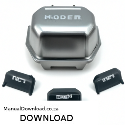
 and repeat the process until all valves are adjusted.
 and let it run for a few minutes. Check for any leaks around the new gasket and listen for any unusual sounds.
 and start the engine. Check for any warning lights on the dashboard related to the clutch system.
 and Install Components
 and fuel mixture entering the engine, thus controlling
 and procedures. If you are not confident in performing these repairs, it is advisable to seek
 and engage the parking brake.
 and correctly routed.