Download 1986 BMW 733i (E23) 7 Series OEM Download Service & Repair Manual Software –

online
Replacing the clutch slave cylinder on a BMW 733i E23 involves several steps. click here for more details on the download manual…..


    The classic BMW 7series E23 745 with custom shock absorbers customized to fit WWM Garage

    Inside BMW Group Classic – the weirder side of luxury, with the BMW 7 series. It’s another new episode of Inside BMW Group Classic! This time, join Marc and Christoph in the garage for a look at some of the 7 …

Here’s a reverse order guide to help you understand the process:

### 7. **Reassemble Components**
– Reinstall any components you had to remove to access the slave cylinder, such as the transmission cover and any shields or brackets.
– Ensure all bolts are tightened to the manufacturer’s specifications.

### 6. **Bleed the Clutch System**
– With the new slave cylinder in place, bleed the clutch system to remove any air.
this typically involves using a brake bleeder kit or having an assistant pump the clutch pedal while you open and close the bleeder valve on the slave cylinder.

### 5. **Install the New Clutch Slave Cylinder**
– Position the new slave cylinder in place.
– Secure it with the mounting bolts and ensure it is properly aligned.

### 4. **Connect the Hydraulic Line**
– Attach the hydraulic line to the new slave cylinder.
– Ensure it is tightened and leak-free.

### 3. **Remove the Old Clutch Slave Cylinder**
– Unbolt the old slave cylinder from its mounting location.
– Disconnect the hydraulic line carefully to prevent spilling fluid.

### 2. **Prepare the Vehicle**
– Safely lift and support the vehicle using Jack stands.
– Remove the undercarriage protection (if applicable) for better access to the transmission.

### 1. **Gather Tools and Materials**
– Ensure you have the necessary tools (wrenches, sockets, pliers), a new clutch slave cylinder, and brake fluid for the hydraulic system.

By following these steps in reverse, you can better understand the overall process of replacing the clutch slave cylinder on a BMW 733i E23. Always refer to a repair manual for specific torque specificationsdownload BMW 733i E23 7 OEM workshop manual and detailed instructions specific to your model.
The crankshaft pulley, also known as the harmonic balancer, is a crucial component of an internal combustion engine. It is mounted on the front end of the crankshaft and serves multiple functions that are essential for the engine’s proper operation. typically made from materials like steel or aluminum, the crankshaft pulley is designed to withstand significant stress and torsional vibrations generated during the engine’s operation.

One of its primary roles is to drive various engine accessories, such as the alternator, power steering pump, water pump, and air conditioning compressor, through a series of belts. The pulley is usually connected to these components via a serpentine belt or multiple V-belts, which allow for efficient power transfer from the engine’s crankshaft.

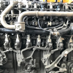
In addition to serving as a drive mechanism, the crankshaft pulley also plays a vital role in reducing engine vibrations. It is designed with a specific mass and damping characteristics that help to absorb and mitigate harmonic vibrations produced by the engine’s firing cycles. this function is critical for maintaining engine balance, enhancing longevity, and ensuring smooth operation.

Furthermore, the crankshaft pulley often features timing marks or a timing belt drive that assists in synchronizing the timing of the engine’s camshaft and other components. In summary, the crankshaft pulley is an integral part of the engine, contributing to both power delivery and the overall smooth functioning of the vehicle.

Download KOMATSU PC200 PC200LC-6 PC210LC-6 Maintenance Manual –

owners manual
Exhaust manifold repair on a Komatsu PC200, PC200LC-6, and PC210LC-6 involves careful planning and execution to restore functionality and prevent further damage. click here for more details on the download manual…..


      #komatsu PC210-8 Monitor display available for sale good condition komatsu PC210-8 Monitor display available for sale #9866905244 https://utsengineers.com https://komatsu-uts.business.site/ …

    Below are detailed steps and tools required for the repair:

    ### Tools and Equipment Needed
    – **Socket Set**: A complete metric socket set will be necessary for removing and replacing bolts.
    – **Wrenches**: Both open-end and box-end wrenches in metric sizes will be required for hard-to-reach areas.
    – **Torque Wrench**: To ensure bolts are tightened to manufacturer specifications, preventing future leaks or failures.
    – **Pry Bar**: Useful for removing stubborn components that may be stuck due to heat and corrosion.
    – **Gasket Scraper**: For cleaning old gasket material off the surfaces.
    – **Wire Brush**: To clean rust from the exhaust manifold and Engine block.
    – **Rags or Towels**: For cleaning surfaces and wiping away debris.
    – **Safety Goggles and Gloves**: Personal protective equipment to protect eyes and hands.
    – **Engine Degreaser**: To clean the area around the exhaust manifold before starting repairs.
    – **Replacement Gaskets**: Ensure you have the correct exhaust manifold gaskets for your specific model.
    – **High-Temperature RTV Sealant**: For additional sealing if required or specified by the manufacturer.
    – **Compressed Air**: For blowing out any debris from the exhaust ports.

    ### Repair Steps
    – **Preparation**:
    – Ensure the machine is parked on level ground and the Engine is cool.
    – Disconnect the battery to prevent any electrical issues while working.
    – Gather all tools and replacement parts before starting to minimize downtime.

    – **Remove the Engine Cover**:
    – If applicable, remove any Engine covers that obstruct access to the exhaust manifold.

    – **Inspect the Area**:
    – Use the wire brush and Engine degreaser to clean around the manifold. This helps prevent debris from falling into the Engine during disassembly.

    – **Disconnect Exhaust and Intake Components**:
    – Remove any pipes or hoses connected to the exhaust manifold.
    – Detach the intake manifold if necessary to gain better access.

    – **Remove Exhaust Manifold Bolts**:
    – Use the appropriate socket and wrench to remove the bolts securing the exhaust manifold to the Engine block.
    – Keep track of the bolt locations as they may be of different lengths.

    – **Remove the Exhaust Manifold**:
    – Carefully pry the exhaust manifold away from the Engine block. Avoid using excessive force to prevent damaging the Engine block.

    – **Inspect the Exhaust Manifold**:
    – Check for cracks, warping, or other damage. If the manifold is severely damaged, it may need to be replaced rather than repaired.

    – **Clean the Surfaces**:
    – Use a gasket scraper to remove old gasket material from the Engine block and exhaust manifold surfaces.
    – Ensure the surfaces are smooth and free from debris.

    – **Install New Gasket**:
    – Place a new exhaust manifold gasket onto the Engine block. Ensure it is properly aligned with the bolt holes.

    – **Reinstall Exhaust Manifold**:
    – Carefully position the exhaust manifold over the gasketdownload KOMATSU PC200 PC200LC 6 PC210LC 6 workshop manual and align it with the bolt holes.
    – Hand-tighten the bolts to hold the manifold in place before fully tightening.

    – **Torque the Bolts**:
    – Using a torque wrench, tighten the manifold bolts to the manufacturer’s specified torque settings in the correct sequence to ensure even pressure.

    – **Reconnect Exhaust and Intake Components**:
    – Reattach any pipes, hoses, or components that were disconnected during the process.

    – **Final Checks**:
    – Inspect all connections to ensure they are secure.
    – Reconnect the battery and start the Engine to check for leaks or unusual noises.

    – **Testing**:
    – Let the Engine run for a few minutes and observe the exhaust manifold area for any signs of leaks. If everything is functioning properly, the repair is complete.

    ### Safety Considerations
    – Always wear safety goggles and gloves to protect yourself from debris and hot surfaces.
    – Ensure the work area is well-ventilated, especially when working with degreasers and sealants.
    – Be cautious of hot components, as the exhaust system can retain heat long after the Engine is turned off.

    By following these steps and using the proper tools, you can effectively repair the exhaust manifold on a Komatsu PC200, PC200LC-6, and PC210LC-6, helping to maintain the machine’s performance and efficiency.
    The fuse box, also known as a fuse panel or fuse block, is a critical component of a vehicle’s electrical system. It serves as a central hub for protecting the various electrical circuits within the automobile by containing fuses that prevent overcurrent conditions. When electrical devices draw more current than what they are designed for, the fuse—typically a small, thin piece of metal within a plastic casing—will melt or break the circuit, effectively stopping the flow of electricity. This protection mechanism helps prevent damage to wiring and electronic components, which could lead to costly repairs or even fire hazards.

    In modern vehicles, the fuse box is usually located under the dashboard, in the Engine compartment, or sometimes in the trunk, depending on the design of the vehicle. Inside the fuse box, each fuse corresponds to a specific electrical component or system, such as headlights, radio, power windows, and other accessories. The fuse box is marked with diagrams or labels indicating the function of each fuse, making it easier for technicians and vehicle owners to identify which fuse may need replacement in case of an electrical issue.

    Additionally, some fuse boxes may include relays, which are electromechanical switches used to control larger electrical loads, further enhancing the vehicle’s electrical management. Regular inspection and maintenance of the fuse box can contribute to the overall reliability and safety of the vehicle’s electrical system, ensuring that all components function as intended and reducing the risk of electrical failures on the road.

    Download 2006 ISUZU ASCENDER Service and Repair Manual –

    purchase
    Adjusting the gear ratio on a vehicle like the Isuzu Ascender typically involves changing the differential gears or the transmission gears. click here for more details on the download manual…..


        Isuzu Ascender Gets A TRANSMISSION For CHRISTMAS *Saved Owner $1,000* This 2003 Isuzu Ascender needs saving, it runs well but won’t move an inch under it’s own power. The owner reached out to Gabe …

      This is a complex process that requires mechanical knowledge and specific tools. Below, I’ll outline the components involved, the steps to adjust the gear ratio, and considerations to keep in mind.

      ### Components Involved in Gear Ratio Adjustment

      1. **Differential Gears**: These are the gears located in the axle assembly. Changing the ring and pinion gear sets alters the gear ratio.

      2. **Transmission Gears**: This includes the internal gears within the transmission system. Adjustments here can also affect the overall gear ratio of the vehicle.

      3. **Axle Assembly**: The part of the vehicle that houses the differential and connects the wheels to the drive train.

      4. **Tools Required**:
      – Floor jack and jack stands
      socket and wrench set
      torque wrench
      – Gear puller
      – Differential setting tool
      – Sealant and gasket kit
      – Dial indicator (for backlash measurement)
      – Measuring tools (calipers, etc.)

      5. **Replacement Gear Set**: If changing the differential gear ratio, you will need a new ring and pinion gear set that matches the desired gear ratio.

      ### Steps to Adjust the Gear Ratio

      #### Preparation
      1. **Safety First**: Park the vehicle on a level surface, engage the parking brake, and wear safety glasses and gloves.

      2. **Lift the Vehicle**: Use a floor jack to lift the rear of the vehicle and secure it on jack stands.

      3. **Remove the Wheels**: Take off the rear wheels to access the axle assembly.

      #### Accessing the Differential
      4. **Remove the Differential Cover**: Unbolt the differential cover using a socket wrench. Be prepared for fluid drainage; have a pan ready to catch the gear oil.

      5. **Inspect the Differential**: Before proceeding, inspect the existing gears for wear or damage.

      #### Removing the Old Gear Set
      6. **Remove the Pinion Gear**:
      – Use a gear puller to take off the pinion gear.
      – Mark the position of shims for reinstallation later.

      7. **Remove the Ring Gear**:
      – Unbolt the ring gear from the differential case.
      – Make sure to keep track of all bolts and shims.

      #### Installing the New Gear Set
      8. **Install the New Ring Gear**:
      – Attach the new ring gear to the differential case using the same bolts. Ensure proper torque specifications are followed.

      9. **Install the New Pinion Gear**:
      position the new pinion gear and set the pinion depth using shims as per the manufacturer’s specifications.

      10. **Adjust Backlash**:
      – Measure the backlash between the ring and pinion gears with a dial indicator.
      – Adjust as necessary by adding or removing shims.

      #### Reassembly
      11. **Reassemble the Differential**:
      replace the differential cover using a new gasket or sealant. Tighten the bolts to the specified torque.

      12. **Reinstall the Wheels**: Put the rear wheels back ondownload ISUZU ASCENDER workshop manual and lower the vehicle.

      #### Final Steps
      13. **Refill the Differential Fluid**: Use the manufacturer-recommended gear oil, filling to the proper level.

      14. **Test Drive**: After ensuring everything is correctly reassembled, take the vehicle for a test drive to listen for unusual noises and check for any leaks.

      ### Considerations
      – **Consult a Professional**: If you’re not experienced with differential work, it’s advisable to consult or hire a professional mechanic.
      – **Gear Ratio Impact**: Changing the gear ratio can affect handling, fuel economy, and performance. Make sure the new ratio is suitable for your driving needs.
      – **Recalibrate Speedometer**: Depending on the gear ratio change, recalibrating the speedometer may be necessary to ensure accurate speed readings.

      ### Conclusion
      Adjusting the gear ratio on an Isuzu Ascender involves significant mechanical work and understanding of the vehicle’s drivetrain system. It’s essential to follow specifications and precautions to ensure a successful and safe adjustment. If uncertain, consider seeking help from an experienced technician.
      The transmission fluid dipstick is a crucial component in vehicles equipped with automatic transmissions. It serves as a measurement tool to check the level and condition of the transmission fluid, which is essential for the proper operation of the transmission system. Typically made of metal or plastic, the dipstick is marked with indicators to show “Full” and “Add” levels, allowing drivers to easily assess whether the fluid is at the appropriate level.

      To use the dipstick, the vehicle owner or mechanic must typically start the engine and allow it to reach normal operating temperature. After shifting through the gears, the dipstick can be removed from its tube, wiped clean, and reinserted to check the fluid level. The fluid’s color and consistency can also be assessed during this process; healthy transmission fluid is usually a bright red or pink color, while dark, burnt, or cloudy fluid may indicate contamination or degradation, necessitating a fluid change.

      Maintaining the correct transmission fluid level is vital, as insufficient fluid can lead to overheating, poor shifting performance, and eventual transmission failure. Regular checks using the dipstick can help prevent such issues, contributing to the longevity and reliability of the vehicle’s transmission system. Thus, the transmission fluid dipstick is not merely a measurement tool but an integral part of vehicle maintenance that ensures smooth operation and helps avoid costly repairs.

      Download 2020 BMW M340d xDrive (G21) 3 Series Touring OEM Download Service & Repair Manual Software –

      book shop
      Performing a wheel alignment on a BMW M340d xDrive G21 3 Touring is a precise task that requires specialized tools and a good understanding of the vehicle’s suspension geometry. click here for more details on the download manual…..


        BMW M340d Xdrive Auto Davit Grey M Sport Pro, Premium, Technology & Comfort Individual Ivory… BMW M340d Xdrive Auto Davit Grey M Sport Pro pack Premium pack Technology pack & Comfort pack Individual Ivory Merino …

        £75k BMW M340i Touring – The AC Schnitzer ACS3 Touring by TRL The ultimate G20 3 Series Touring, absolutely love this car! New BMW quotes/sales, email Tony Lewis – trldeals@outlook.com …

      Below is a detailed guide on the components involved in the procedure, the types of alignments, and the steps to perform the alignment.

      ### Components Involved in Wheel Alignment

      1. **Alignment Rack**: A specialized platform where the car is positioned for alignment measurements. It has sensors and cameras to measure wheel angles.

      2. **Alignment Equipment**: Digital alignment machines that read the angles of the wheels, usually comprising:
      – **Sensors**: Attached to each wheel to measure camber, caster, and toe angles.
      – **Computer Interface**: Displays real-time measurements, specifications, and adjustments needed.

      3. **Vehicle Specifications**: The manufacturer’s specifications for camber, caster, and toe for the M340d xDrive G21, usually found in the service manual.

      4. **Adjustment Components**: Various parts that may need adjustment during the alignment process, including:
      – **Camber Bolts**: Used to adjust the camber angle.
      – **Toe adjustment Screws**: Typically located on the tie rod ends for adjusting toe.
      – **Caster Adjustment**: Usually not adjustable on most cars, but if it is, it will involve adjustments to the upper control arms.

      5. **Tools Required**:
      – Basic hand tools (wrenches, sockets)
      – Torque wrench for tightening bolts to manufacturer specifications
      – Leveling tools to ensure the vehicle is properly positioned

      ### Types of Alignments

      1. **Front-End Alignment**: Adjusts only the front wheels’ angles.
      2. **Thrust Angle Alignment**: Ensures that the rear wheels are aligned relative to the front wheels.
      3. **Four-Wheel Alignment**: Adjusts all four wheels for optimal performance.

      ### Step-by-Step Procedure for Wheel Alignment

      #### Step 1: Preparation

      1. **Park the Vehicle**: Ensure the vehicle is on a flat, level surface.
      2. **Inspect Tires**: Check for uneven wear, proper inflation, and damage. Replace if necessary.
      3. **Check Suspension Components**: Inspect for wear or damage in the suspension, steering, and other components. Replace any faulty parts.

      #### Step 2: Set Up the Alignment Rack

      1. **Position the Vehicle**: Drive the vehicle onto the alignment rack, ensuring that it is centered and straight.
      2. **Secure the Vehicle**: Use wheel chocks and engage the parking brake.

      #### Step 3: Attach Alignment Sensors

      1. **Install Sensors**: Attach the alignment sensors to each wheel as per the manufacturer’s instructions.
      2. **Calibrate the System**: Ensure the alignment machine is calibrated and reset before taking measurements.

      #### Step 4: Take Initial Measurements

      1. **Measure Wheel Angles**: Use the alignment machine to read the initial camber, caster, and toe angles.
      2. **Record Measurements**: Document the readings for comparison with the manufacturer’s specifications.

      #### Step 5: Make Adjustments

      1. **Adjust Camber**:
      – Loosen the camber bolts on the top of the strut assembly (if applicable).
      – Adjust the angle to match specifications and retighten.

      2. **Adjust Toe**:
      – Locate the tie rod ends.
      – Use a wrench to turn the adjustment screws to achieve the desired toe angle.

      3. **Adjust Caster** (if applicable):
      – If the vehicle has caster adjustment, this might involve moving the upper control arm. Follow the manufacturer’s specifications.

      #### Step 6: Recheck Measurements

      1. **Take New Measurements**: After adjustments, measure the wheel angles again to ensure they are within specifications.
      2. **Fine-Tune Adjustments**: If necessary, repeat the adjustment process until all angles are correct.

      #### Step 7: Test Drive

      1. **Perform a Test Drive**: Ensure the vehicle drives straightdownload BMW M340d xDrive G21 3 Touring OEM workshop manual and handles correctly.
      2. **Recheck Alignment**: It’s advisable to recheck alignment after a short test drive since suspension components may settle.

      #### Step 8: Final Documentation

      1. **Document Results**: Record the final measurements and adjustments made for future reference.
      2. **Provide Customer with Report**: If this is a service job, provide the customer with the alignment report.

      ### Conclusion

      Performing a wheel alignment on a BMW M340d xDrive G21 requires a good understanding of the vehicle’s suspension systems, the right tools, and a methodical approach. Following the above steps carefully will help ensure optimal handling, tire wear, and overall performance of the vehicle. If unsure, consider consulting a professional technician or service center with experience in BMW vehicles.
      The engine bay, also known as the engine compartment, is a crucial area in a vehicle that houses the engine and various associated components. Typically located at the front of the car, although in some designs it can be found in the rear, the engine bay is designed to provide access to the engine for maintenance, repair, and inspection.

      The engine bay is not just a simple enclosure; it is a meticulously engineered space that accommodates essential parts such as the engine itself, transmission, radiator, battery, and various fluid reservoirs, such as those for oil, coolant, and windshield washer fluid. The layout within the engine bay is vital for optimal engine performance and cooling efficiency, as it allows for proper airflow and minimizes overheating.

      Additionally, the engine bay often contains wiring harnesses and various sensors that are integral to the vehicle’s electronic systems. The accessibility of the engine bay is a key consideration in automotive design, as mechanics and technicians require sufficient space to work when performing routine maintenance or troubleshooting issues.

      Moreover, the engine bay plays a role in the overall safety of the vehicle. It can include crumple zones designed to absorb impact during a collision, protecting both the engine and passenger cabin. In modern vehicles, the engine bay is also increasingly influenced by regulations regarding emissions and noise, leading to the integration of components that help reduce environmental impact. Overall, the engine bay is an essential element of automotive engineering, combining functionality, safety, and efficiency.

      Download BMW 518i 1990 Repair Service Manual –

      repair
      ### Brake Rotor Replacement on a BMW 518i – **Safety Precautions** – Ensure the car is on a flat surface. click here for more details on the download manual…..


        BMW E34 M5 Cylinder Head Cleaning – Engine Rebuild and Full Automotive Restoration shorts #bmw #cars #automotive #bmwe34 #restoration #engine Welcome to WeWrench. My name is Michael Dey and my goal is …

        Lowering My E34 On OE Sport Suspension! | Strut/Shock replacement DIY + H&R OE Sport Springs It’s time to lower my E34. I put together my own OE style setup to retain as much of the original ride quality as possible while …

      ### Brake Rotor Replacement on a BMW 518i

      – **Safety Precautions**
      – Ensure the car is on a flat surface.
      – Engage the parking brake and use wheel chocks to prevent movement.
      – Wear safety glasses and gloves for protection.

      – **Gather Necessary Tools and Materials**
      – **Jack and Jack Stands**: Used to lift and secure the vehicle safely.
      – **Lug Wrench**: To remove wheel lug nuts.
      – **Socket Set**: Typically includes 10mm, 13mm, or 15mm sockets for caliper bolts.
      – **Torque Wrench**: For correctly tightening bolts to the manufacturer’s specifications.
      – **Brake Cleaner**: To clean the new rotors and brake components.
      – **C-clamp or Brake Caliper Tool**: To retract the caliper piston.
      – **New Brake Rotors**: Ensure they are compatible with the BMW 518i.
      – **New Brake Pads**: Recommended to replace with rotors for optimal performance.
      – **Flathead Screwdriver**: For prying or removing clips if necessary.

      – **Preparation**
      – Loosen the lug nuts slightly while the car is on the ground for easier removal.
      – Use the jack to lift the front or rear of the vehicle, depending on which rotors you are replacing.
      – Secure the vehicle with jack stands to ensure stability.

      – **Removing the Wheel**
      – Fully remove the loosened lug nuts and take off the wheel.
      – Store the wheel in a safe place to avoid damage.

      – **Removing the Brake Caliper**
      – Locate the caliper bolts; these are usually found on the back of the caliper.
      – Use the socket set to remove the caliper bolts.
      – Carefully slide the caliper off the brake rotor. Do not let it dangle; support it using a bungee cord or hang it securely to prevent strain on the brake line.

      – **Removing the Old Brake Rotor**
      – If the rotor is secured with screws, use a screwdriver or socket to remove them.
      – If the rotor is stuck due to corrosion, gently tap it with a hammer to loosen it.
      – Slide the rotor off the hub. If it’s tight, apply a bit of penetrating oil to ease removal.

      – **Preparing the New Rotor**
      – Clean the new rotor with brake cleaner to remove any protective oil or residue.
      – Compare the new rotor with the old one to ensure they match in size and specifications.

      – **Installing the New Rotor**
      – Place the new rotor onto the hub, ensuring it sits flush against the mounting surface.
      – If applicable, reinsert any screws to secure the rotor in place.

      – **Reinstalling the Brake Caliper**
      – Before reinstalling the caliper, use the C-clamp or brake caliper tool to compress the piston back into the caliper.
      – Position the caliper over the new rotor and align it with the mounting bracket.
      reinsertdownload BMW 518i workshop manual and tighten the caliper bolts securely.

      – **Reinstalling the Wheel**
      – Place the wheel back onto the hub and hand-tighten the lug nuts.
      – Lower the vehicle off the jack stands and onto the ground.
      – Use the torque wrench to tighten the lug nuts to the manufacturer’s specifications.

      – **Testing the Brakes**
      – Before driving, pump the brake pedal several times to ensure proper caliper engagement and brake pad seating.
      – Check for any unusual noises or signs of misalignment.

      – **Final Check**
      – Inspect the brake system for leaks or loose components.
      – Ensure the area around the brakes is clean and free from debris.

      – **Dispose of Old Parts**
      – Properly dispose of the old rotors and any other replaced components at a recycling center or appropriate disposal site.

      Following these detailed steps will help ensure a successful brake rotor replacement on your BMW 518i. Always refer to the vehicle’s service manual for specific torque specifications and additional guidance.
      The oil filter is a vital component of an internal combustion engine, designed to remove contaminants from engine oil that can accumulate over time during vehicle operation. Engine oil serves multiple purposes, including lubricating moving parts, reducing friction, cooling engine components, and cleaning the engine by suspending dirt and debris. However, as the oil circulates through the engine, it can pick up various impurities such as dirt, metal shavings, soot, and other particulates, which can degrade its performance and, subsequently, the engine’s efficiency.

      The oil filter works by trapping these contaminants, allowing clean oil to continuously circulate through the engine. Typically cylindrical in shape, oil filters come in two main types: full-flow filters and bypass filters. Full-flow filters allow all the oil to pass through the filter medium, while bypass filters only allow a portion of the oil to be filtered, redirecting the rest back into the system. The filter medium itself is often made from synthetic or cellulose materials that effectively capture particles while allowing oil to flow through.

      Regularly replacing the oil filter is crucial for maintaining engine health. A clogged or dirty oil filter can lead to reduced oil flow, increased engine wear, and potential overheating. Therefore, it is recommended to change the oil filter during routine oil changes, which is typically every 3,000 to 7,500 miles, depending on the vehicle and oil type. Neglecting this maintenance can lead to serious engine issues and costly repairs.

      Download 2002 MAZDA CAPELLA Service and Repair Manual –

      shop
      Replacing the clutch pressure sensor on a Mazda Capella involves several steps and tools. click here for more details on the download manual…..


        MAZDA 616 S2 RESTORATION PT 2 1st GEN MAZDA CAPELLA RESTORATION PT 2. Doing the body work, cutting, welding, grinding, body filling, sanding and all the …

        Fixing low hanging door handle and replacing clip in Mazda Capella / RX2 This is a video on how I fixed the passenger side door handle on my Mazda Capella / Rx2. The problems were 1/hard to open …

      Below is a detailed guide to help you through the process.

      ### Tools and Equipment Needed:
      – **Socket Set**: A variety of sockets (metric) to remove bolts and nuts.
      – **Wrenches**: Open-end and box-end wrenches for access to tight spaces.
      – **Screwdrivers**: Both Phillips and flat-head for removing fasteners.
      – **Torque Wrench**: To ensure bolts are tightened to the manufacturer’s specifications.
      – **Pliers**: For removing clips or retaining rings.
      – **Wire Cutters/Strippers**: In case of needing to repair or replace wiring.
      – **Multimeter**: For testing electrical connections and sensor functionality.
      – **Rags/Paper Towels**: To clean up any fluid spills and for general use.
      – **Safety Glasses**: To protect your eyes during the procedure.
      – **Gloves**: To keep your hands clean and protected.

      ### Replacement Steps:

      – **Locate the Clutch Pressure Sensor**:
      – The clutch pressure sensor is typically located on or near the clutch master cylinder or transmission housing. Refer to your vehicle’s service manual for the exact location.

      – **Disconnect the Battery**:
      – Start by disconnecting the negative terminal of the battery to prevent any electrical shorts or shocks while working on the vehicle.

      – **Access the Sensor**:
      – Depending on the layout of your Mazda Capella, you may need to remove various components (like the air intake or battery) to gain access to the clutch pressure sensor.

      – **Remove the Electrical Connector**:
      – Carefully unplug the electrical connector from the clutch pressure sensor. Use pliers or your fingers to gently release any clips holding it in place.

      – **Unbolt the Sensor**:
      – Using the appropriate socket, remove the bolts securing the clutch pressure sensor to the housing. Be cautious not to drop any bolts into the engine bay.

      – **Remove the Old Sensor**:
      – Once the bolts are removed, gently pull the old sensor out of its housing. inspect the O-ring or gasket for damage, as this may need replacing as well.

      – **Prepare the New Sensor**:
      – If the new sensor does not come with an O-ring or gasket, install a new one to ensure a proper seal. Apply a small amount of engine oil to the O-ring for easier installation.

      – **Install the New Sensor**:
      – Position the new clutch pressure sensor into the housing and secure it with the bolts you previously removed. Be careful not to overtighten, as this may damage the sensor or housing.

      – **Reconnect the Electrical Connector**:
      – Plug the electrical connector back into the new sensor. Ensure it clicks into place securely.

      – **Reassemble Any Removed Components**:
      – If you removed any parts to access the sensor, reattach them in the reverse order of removal. Ensure all boltsdownload MAZDA CAPELLA workshop manual and clips are tightened properly.

      – **Reconnect the Battery**:
      – Reconnect the negative terminal of the battery. Ensure the connection is secure.

      – **Test the New Sensor**:
      – Start the vehicle and check for any warning lights on the dashboard. Use a multimeter to verify the sensor is functioning correctly if needed.

      – **Check for Leaks**:
      – After the installation, inspect the area around the new sensor for any signs of fluid leaks.

      ### final Tips:
      always refer to the vehicle’s service manual for specific torque specifications and guidelines.
      – If at any point you feel uncomfortable performing the replacement, consider seeking help from a professional mechanic.
      – Keep the work area clean and organized to avoid losing small parts during the process.

      Following these steps should help you successfully replace the clutch pressure sensor on your Mazda Capella.
      The water pump is a crucial component of an automotive cooling system, designed to circulate coolant throughout the engine and radiator. Its primary function is to maintain optimal engine temperature, preventing overheating and ensuring efficient operation. The pump is typically driven by the engine’s crankshaft via a belt or chain, which means it operates in sync with the engine’s performance.

      The water pump consists of a rotor, impeller, and housing. When the engine runs, the impeller spins, creating a pressure differential that draws coolant from the radiator and pushes it through the engine block and cylinder head. This circulation helps absorb heat generated by the engine during combustion. Once the coolant reaches a certain temperature, it flows back to the radiator, where it releases heat to the atmosphere. This continuous cycle is essential for keeping the engine within its operating temperature range, thereby enhancing performance and longevity.

      Over time, water pumps can wear out due to factors like corrosion, bearing failure, or leaks, which can lead to coolant loss and potential engine overheating. Regular maintenance and checks are essential to ensure the water pump functions effectively. Signs of a failing water pump may include coolant leaks, unusual noise, or engine temperature fluctuations. Replacing a faulty water pump promptly is vital to prevent severe engine damage and maintain the vehicle’s reliability.

      Download 1998 SKYLARK Service and Repair Manual –

      do your own repairs
      Air suspension systems can be complex, but I can break it down into simpler steps for you. click here for more details on the download manual…..


        How to Change a Ignition Cylinder in a 1972 Buick Skylark Here we are changing out the ignition cylinder in our 1972 Buick Skylark.

        Skylark Road Music from #Uppbeat (free for Creators!): https://uppbeat.io/t/faodail/frayed.

      Here’s a basic guide on how to repair air suspension on a Buick Skylark, or a similar vehicle, assuming you have a basic understanding of tools and safety. Please remember that if you feel uncomfortable at any step, it’s always best to seek help from a professional mechanic.

      ### Tools and Materials Needed:
      – Wrenches and sockets
      – Screwdrivers
      – Pliers
      – Replacement air suspension parts (like air bags or compressor)
      – Safety glasses
      – Jack and jack stands
      – Tire chocks

      ### Step-by-Step Guide:

      1. **Safety First**:
      – Park your vehicle on a flat surface.
      – Turn off the ignition and remove the keys.
      – Use tire chocks to prevent the car from rolling.
      – Wear safety glasses to protect your eyes.

      2. **Lift the Vehicle**:
      – Use a jack to lift the rear or front of the vehicle (depending on which suspension needs repair).
      – Once lifted, place jack stands under the vehicle to keep it stable while you work.

      3. **Identify the Problem**:
      – Check for visible signs of damage on the air suspension components, such as air bags or the compressor.
      – Look for leaks or cracks. If the air bags are sagging, they may need replacing.

      4. **Remove the Old Parts**:
      – If you need to replace the air bag:
      – Locate the air bag connected to the suspension. You may need to remove some components to access it.
      – Disconnect the air lines carefully. You may have to press a small tab or use pliers to release the fitting.
      – Unbolt the air bag from its mounting points using the appropriate socket or wrench.
      – If replacing the compressor:
      – Locate the compressor unit, usually found near the rear of the vehicle.
      – Disconnect the electrical connectors and air lines.
      – Remove the mounting bolts and take out the compressor.

      5. **Install the New Parts**:
      – For the air bag:
      – Position the new air bag in place and secure it with the mounting bolts.
      – Reconnect the air lines, ensuring they are snug and leak-free.
      – For the compressor:
      – Mount the new compressor in place and secure it with bolts.
      – Reconnect the electrical connectors and air lines.

      6. **Check for Leaks**:
      – Before lowering the vehicle, turn on the ignition (don’t start the engine) to allow the compressor to run.
      – Listen for any unusual sounds and check the connections for air leaks. Use soapy water on the connections; bubbles will form if there’s a leak.

      7. **Lower the Vehicle**:
      – Once you’ve confirmed everything is securedownload SKYLARK workshop manual and there are no leaks, carefully remove the jack stands and lower the vehicle back to the ground.

      8. **Final Check**:
      – Start the vehicle and allow it to run for a few minutes. Observe the air suspension system to ensure it raises and lowers properly.
      – Take a short drive to see if the suspension feels stable and functions correctly.

      ### Important Tips:
      – Always consult your vehicle’s service manual for specific instructions related to your model.
      – If you’re unsure about any step, consider asking for help from someone with more mechanical experience or hiring a professional mechanic.
      – Working on suspension systems can affect vehicle safety; take your time and ensure everything is done correctly.

      By following these steps, you should be able to perform a basic air suspension repair on a Buick Skylark. Good luck, and remember to prioritize safety!
      A center cap is a crucial component of a vehicle’s wheel, typically positioned in the center of the wheel hub. It serves both functional and aesthetic purposes. Functionally, the center cap helps to cover and protect the wheel hub, which is the area where the wheel attaches to the axle. This protection is essential as it prevents dirt, debris, and moisture from entering the hub assembly, which could potentially lead to corrosion or damage to critical components like the wheel bearings.

      In terms of aesthetics, center caps contribute significantly to the overall appearance of the wheel. They are often designed to match the vehicle’s brand and style, showcasing the manufacturer’s logo or emblem. This branding not only adds a polished look to the wheels but also enhances the vehicle’s identity. Center caps come in various sizes, materials, and designs, depending on the type of vehicle and the specific wheel model. Some may be made from plastic, while others are crafted from metal for added durability.

      Additionally, center caps can vary in their attachment methods; some are secured with clips or screws, while others may snap into place. In the aftermarket world, enthusiasts often customize center caps to enhance their vehicle’s personality or to match specific designs, making them a popular Accessory in automotive customization. Overall, while small in size, center caps play a significant role in both the functionality and appearance of a vehicle’s wheels.

      Download CATERPILLAR CAT 3208 Diesel Truck Engine Workshop Manual –

      online
      Repairing an alternator on a Caterpillar CAT 3208 truck engine can seem daunting, but with a clear step-by-step approach, you can tackle it. click here for more details on the download manual…..


        The Cat 3208 Engine. Know Your Engine. Engine Design And Problems. Cat 3208. The Cat 3208 had along production run and can still be found in several different industries. This video goes over the engine …

        She replaces the Main Engine Starter on a caterpillar 3208 Watch as this beautiful blond tackles a heavy-duty diesel engine starter, specifically the Caterpillar 3208ta. This video showcases …

      Here’s a simple guide to help you understand the process, even if you have little mechanical experience.

      ### What is an Alternator?
      The alternator is an important part of your truck’s electrical system. It generates electricity to charge the battery and power electrical systems while the engine is running.

      ### Tools You’ll Need:
      1. **Basic Hand Tools:** Wrenches, socket set, screwdrivers
      2. **Safety Gear:** Gloves and safety glasses
      3. **Multimeter:** For testing electrical connections
      4. **Replacement Parts:** If needed (new alternator or repair kit)

      ### Step-by-Step Repair Process:

      #### 1. **Safety First:**
      – Make sure the truck is parked on a flat surface and the engine is turned off.
      – Disconnect the battery by removing the negative (-) terminal first. This prevents any electrical shock or short circuits.

      #### 2. **Locate the Alternator:**
      – Open the hood of the truck.
      – The alternator is usually mounted on the front side of the engine. It looks like a round metal piece with a belt attached to it.

      #### 3. **Inspect the Alternator:**
      – Check for any visible signs of damage, such as cracks or loose wires.
      – Look for any broken or worn belts. If the belt is damaged, it may need to be replaced.

      #### 4. **Remove the Belt:**
      – If the belt is in good condition and you’re just checking the alternator, you can skip this step. Otherwise, use a wrench to loosen the tensioner pulley (the part that holds the belt tight) and slide the belt off the alternator.

      #### 5. **Disconnect Electrical Connections:**
      – Carefully unplug any electrical connectors attached to the alternator. Take a picture or make a note of where each wire goes for reassembly.

      #### 6. **Remove the Alternator:**
      – Use a socket wrench to unscrew the bolts that hold the alternator in place. There are usually two or three bolts. Keep these in a safe place to reuse later.

      #### 7. **Install the New or Repaired Alternator:**
      – If you’re replacing the alternator, take the new unit and place it where the old one was. Secure it with the bolts you removed earlier.
      – If you’re repairing the alternator, follow the repair kit instructions to fix any internal components.

      #### 8. **Reconnect the Electrical Connections:**
      – Reattach the electrical connectors to the new or repaired alternator, referring to your earlier notes or pictures.

      #### 9. **Reinstall the Belt:**
      – Place the belt back onto the alternator. Use the tensioner pulley to tighten it back into place. Make sure the belt is properly seated.

      #### 10. **Reconnect the Battery:**
      – Reconnect the negative (-) terminal of the battery first. This is important to prevent any sparks.

      #### 11. **Test the Alternator:**
      – Start the enginedownload CATERPILLAR CAT 3208 Truck Engine workshop manual 
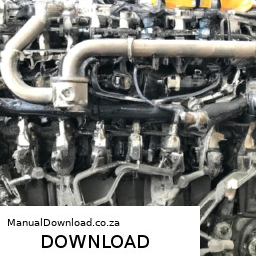
and check that the alternator is working. Use a multimeter to check the voltage; it should be around 13.8 to 14.4 volts when the engine is running. If the voltage is outside this range, you may need to troubleshoot further.

      ### Final Tips:
      – Always consult the owner’s manual for specific details related to your truck.
      – If you feel unsure at any step, don’t hesitate to ask for help from someone with more mechanical experience.
      – Keep your workspace organized and clean to avoid losing small parts.

      With patience and careful attention to detail, you can successfully repair the alternator on your Caterpillar CAT 3208 truck engine!
      A jack stand is a critical safety device used in automotive maintenance and repairs to support a vehicle after it has been lifted with a hydraulic or mechanical jack. Typically constructed from sturdy materials like steel or aluminum, jack stands are designed to provide a secure and stable platform for the vehicle, ensuring that it remains elevated and does not collapse during servicing.

      When a car is lifted using a jack, it is crucial to place jack stands underneath the vehicle to prevent potential accidents. Jacks can fail, especially if they are overloaded or malfunction, and jack stands serve as a fail-safe measure. They come in various sizes and weight capacities, allowing users to select the appropriate stand for their specific vehicle type and weight.

      Most jack stands have a ratchet mechanism or a pin-locking design that allows for height adjustment. This feature enables users to set the stands at the desired height to accommodate different vehicle models and provide adequate clearance for access to the undercarriage.

      Using jack stands is essential for tasks such as changing tires, performing brake work, or inspecting the undercarriage. Safety is paramount when working under a vehicle; therefore, employing jack stands is a best practice that ensures both the safety of the technician and the integrity of the vehicle during repairs. Overall, jack stands are indispensable tools in any mechanic’s arsenal, contributing significantly to safe automotive servicing.

      Download Kobelco K905LC-II Parts-

      do your own repairs
      Replacing the input shaft bearing on a Kobelco K905LC II excavator involves several steps, and it’s important to follow the manufacturer’s guidelines for safety and accuracy. click here for more details on the download manual…..


        Engine Mounting Rubber 2416Z574 2416Z573 2416Z498 for Kobelco K904-2 SK100-3 SK120-3 SK120LC-3 8 PCS Engine Mounting Rubber Cushion 2416Z574 2416Z573 2416Z498 for Kobelco Excavator K904-2 K904L-2 K905-2 …

      Below is a detailed description of the components and the process involved in replacing the input shaft bearing.

      ### Components Involved:

      1. **Input shaft Bearing**: This is the bearing that supports the input shaft and allows it to rotate smoothly. It is crucial for the proper functioning of the drivetrain.

      2. **Input Shaft**: The shaft that transmits power from the engine to the drivetrain. It connects to the transmission.

      3. **Bearing Housing**: This is the component that holds the input shaft bearing in place. It is often bolted to the transmission case.

      4. **Gasket/Seals**: Gaskets and seals prevent leaks and keep contaminants out of the bearing housing.

      5. **Fasteners**: Bolts and nuts that secure the bearing housing and other components.

      6. **Tools**: Common tools required for this job include wrenches, sockets, a bearing puller, a hammer, a torque wrench, and possibly special tools designed for bearing installation.

      ### Tools Required:

      – Socket set
      – Wrench set
      – Torque wrench
      – Bearing puller
      – Hammer
      – Screwdrivers
      – Pliers
      – Clean cloths
      – Lubricant (grease or oil)
      – Safety equipment (gloves, goggles)

      ### Step-by-Step Replacement Procedure:

      1. **Safety Precautions**:
      – Park the excavator on a flat surface and engage the parking brake.
      – Disconnect the battery to prevent any electrical hazards.
      – Use safety glasses and gloves for protection.

      2. **Remove the Cover**:
      – Locate the cover over the input shaft bearing. This may involve removing access panels or covers.
      – Use the appropriate tools to remove any bolts or fasteners securing the cover.
      – Carefully lift off the cover and set it aside.

      3. **Drain Transmission Fluid**:
      – If necessary, drain the transmission fluid to prevent spills during the bearing replacement.
      – Locate the drain plug on the transmission case and remove it to allow the fluid to drain completely.

      4. **Remove the Input Shaft**:
      – Depending on the design, you may need to remove other components or parts that obstruct access to the input shaft.
      – Use a bearing puller to remove the input shaft from its position if it is stuck.
      – Gently tap it out with a hammer if necessary, ensuring that you do not damage any surrounding components.

      5. **Remove the Old Bearing**:
      – Once the input shaft is out, access the bearing housing where the input shaft bearing is located.
      – Use the bearing puller to remove the old input shaft bearing. Be careful not to damage the bearing housing.
      – Inspect the bearing housing for any signs of wear or damage.

      6. **Clean the Area**:
      – Clean the bearing housingdownload Kobelco K905LC II Parts workshop manual and the surrounding area to remove any debris or old gasket material.
      – Use a clean cloth and appropriate cleaning solution if necessary.

      7. **Install the New Bearing**:
      – Apply a thin layer of lubricant to the new input shaft bearing.
      – Carefully place the new bearing into the bearing housing.
      – Use a bearing installation tool or a soft-faced hammer to tap the bearing into place gently. Ensure it is seated evenly.

      8. **Reinstall the Input Shaft**:
      – Align the input shaft with the new bearing and insert it back into position.
      – Ensure it is seated correctly and rotates smoothly.

      9. **Reattach the Cover**:
      – If there is a gasket or seal, replace it with a new one to prevent leaks.
      – Reattach the cover over the input shaft bearing and secure it with the appropriate fasteners.
      – Torque the bolts to the manufacturer’s specifications.

      10. **Refill Transmission Fluid**:
      – If you drained the transmission fluid earlier, refill it to the appropriate level.
      – Check for any leaks around the newly installed bearing.

      11. **Reconnect the Battery**:
      – Reconnect the battery and ensure all electrical connections are secure.

      12. **Test the Excavator**:
      – Start the excavator and perform a test run to ensure everything is functioning correctly. Listen for any unusual noises and check for leaks.

      ### Conclusion:
      Replacing the input shaft bearing on a Kobelco K905LC II excavator requires careful attention to detail and adherence to safety protocols. Following these detailed steps will help ensure a successful replacement. Always consult the operator’s manual or service manual for specific torque values and additional procedures related to your excavator model.
      The grille emblem is a distinctive and often iconic component found on the front of many vehicles, typically positioned prominently within the vehicle’s grille. This emblem serves multiple purposes, both functional and aesthetic. Primarily, it acts as a branding element, showcasing the manufacturer’s logo or name, which contributes to the vehicle’s identity and recognition. Whether it features a stylized letter, a symbol, or a combination of both, the grille emblem is a critical aspect of a car’s overall design language.

      Beyond branding, the grille emblem can play a role in the vehicle’s aerodynamics. In some cases, it is designed to enhance airflow to the engine or cooling systems, which can be crucial for performance. The placement of the emblem often aligns with the vehicle’s design philosophy, complementing the lines and contours of the front fascia.

      Additionally, grille emblems can vary in materials and finishes, ranging from chrome and metallic finishes to more modern, minimalist designs using plastic or composite materials. Some emblems are illuminated, adding a contemporary touch and improving visibility in low-light conditions. The grille emblem not only contributes to the visual appeal of the vehicle but also helps establish a connection between the driver and the brand, making it a significant element in automotive design and marketing.

      Download 2005 BMW Z4 (E85) OEM Download Service & Repair Manual Software –

      repair
      Flushing the brake fluid in a BMW Z4 E85 is an important maintenance task that helps ensure your braking system works effectively. click here for more details on the download manual…..


        3 SERIOUS COMMON ISSUES – BMW Z4 (e85) | 2003 – 2008 production years

        Remove Automatic Shift Knob | BMW Z4 2003-2008 A/T Knobs LCI Black: https://geni.us/UkXo LCI Beige: https://geni.us/ujk1hga LCI Black Chrome: https://geni.us/E3SbXA LCI Beige …

      Brake fluid can absorb moisture over time, which can reduce its effectiveness and potentially cause brake failure. Here’s a step-by-step guide to performing a brake fluid flush on your BMW Z4 E85, explained in simple terms:

      ### What You’ll Need:
      1. **New Brake Fluid**: Make sure to use the correct type of brake fluid, typically DOT 4 for BMW vehicles. Check your owner’s manual to confirm.
      2. **Brake Bleeder Kit**: This can be a one-person bleeder or a traditional two-person setup.
      3. **Wrench**: A 10mm or the size that fits your brake bleeder screws.
      4. **Clear Tubing**: To connect to the bleeder valve and collect old fluid.
      5. **Container**: To catch the old brake fluid.
      6. **Rags/Paper Towels**: For cleaning up spills.
      7. **Jack and Jack Stands**: To lift the car safely if needed.
      8. **Safety Glasses and Gloves**: To protect your eyes and skin from brake fluid.

      ### Steps to Flush Brake Fluid:

      #### 1. **Safety First**
      park the car on a flat surface and engage the parking brake.
      – Put on safety glasses and gloves.

      #### 2. **Access the Brake System**
      – If necessary, lift the car with a jack and secure it with jack stands.

      #### 3. **Locate the Brake Fluid Reservoir**
      – Open the hood and find the brake fluid reservoir. It’s usually located near the back of the engine bay, towards the driver’s side.

      #### 4. **Remove Old Brake Fluid**
      – Use a turkey baster or squeeze bulb to remove as much old brake fluid from the reservoir as possible. This will make it easier to replace with the new fluid.

      #### 5. **Add New Brake Fluid**
      – Fill the reservoir with new brake fluid up to the “max” line. This ensures that the system has enough fluid to work with during the flush.

      #### 6. **Bleed the Brakes**
      – **Start with the Wheels Farthest from the Brake Master Cylinder**: Typically, this means starting with the right rear wheel, then left rear, right front, and finally left front.
      – **Locate the Bleeder Valve**: This is usually a small screw on the brake caliper.
      – **Attach the Clear Tubing**: Put one end of the tubing over the bleeder valve and place the other end in the container to catch the old fluid.

      #### 7. **Open the Bleeder Valve**
      – Use the wrench to turn the bleeder valve counterclockwise to open it slightly. This will allow old brake fluid to escape.
      – **Have a Helper Pump the Brake Pedal**: If you have someone to help, have them pump the brake pedal several times and then hold it down.
      – **Close the Bleeder Valve**: While they’re holding the pedal down, quickly close the valve to prevent air from entering the system.
      – **Repeat**: Open the valve again,download BMW Z4 E85 OEM workshop manual and let them pump the brakes. Repeat this process until you see clear, new brake fluid in the tubing. Keep an eye on the reservoir and top it off as needed to avoid running it dry.

      #### 8. **Finish Up**
      – Once all wheels have been bled and you see clean fluid coming out, close all bleeder valves tightly.
      – Refill the brake fluid reservoir to the “max” line.
      – Clean up any spills immediately, as brake fluid can damage paint and other surfaces.

      #### 9. **Test the Brakes**
      – Before driving, pump the brake pedal a few times to ensure the brakes feel firm.
      – Check the fluid level one last time and make sure there are no leaks around the calipers or bleeder valves.

      #### 10. **Dispose of Old Brake Fluid Properly**
      – Take the old brake fluid to a local auto parts store or recycling center for proper disposal.

      ### Final Notes:
      Performing a brake fluid flush is a straightforward process, but if at any point you feel uncomfortable or unsure, it’s best to consult a professional mechanic. Regular maintenance of your braking system is vital for your safety on the road.
      A fender is a crucial component of a vehicle’s body, primarily designed to cover the wheel wells and provide protection to the car’s bodywork and passengers from road debris, mud, and water that may be kicked up by the tires. Typically made from materials such as steel, aluminum, or composite plastics, fenders play both functional and aesthetic roles in automotive design.

      Functionally, fenders help to safeguard the vehicle’s body from scratches, dents, and other forms of damage caused by stones or other debris that can be thrown up while driving. They also serve to reduce the amount of dirt and water that can be splashed onto the vehicle and its passengers, enhancing safety and comfort. In addition, fenders contribute to the overall aerodynamics of a vehicle, influencing airflow and reducing drag, which can improve fuel efficiency.

      Aesthetically, fenders are integral to the car’s design language and style. They can be shaped and styled in various ways to complement the vehicle’s overall look, contributing to its visual appeal. In performance cars, fenders are often designed to be wider to accommodate larger tires and to hint at the vehicle’s sporty capabilities.

      In modern automotive design, fenders can also house various components, including turn signals and other lighting elements, and may be designed to facilitate airflow to the brakes or engine. Overall, the fender is an essential component that balances protection, functionality, and aesthetics in vehicle design.