Download 2011 Terex Wheel Loader TL100 Operating Manual –

online
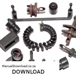
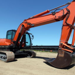
Replacing the clutch release bearing on a Terex Wheel Loader TL100 involves several detailed steps and requires specific tools and equipment. click here for more details on the download manual…..


    Terex TL100 Compact Loading Shovel Terex TL100 Shovel. Dec 2012 (62). 3022 hours. 405/70- x 20 bibload style tyres – 20%. RDS weighlog. Deutz 55KW (75HP …

    Below is a comprehensive guide to assist you in the process.

    – **Preparation and Safety**
    – **Personal Protective Equipment (PPE):** Ensure you are wearing appropriate PPE, including gloves, safety glasses, and steel-toed boots.
    – **Work Area:** Clear the workspace and ensure it is well-lit and free of hazards.
    – **Owner’s Manual:** Have the TL100 owner’s manual on hand for specific instructions and torque specifications.

    – **Tools and Equipment Required**
    – **Basic Hand Tools:**
    – **Socket Set:** Metric and standard sockets for various bolts.
    – **Wrenches:** A set of open-end and box-end wrenches for different sizes.
    – **Screwdrivers:** Flathead and Phillips screwdrivers for various fasteners.
    – **Specialized Tools:**
    – **Clutch Alignment Tool:** To ensure the clutch is properly aligned during reassembly.
    – **Bearing Puller or Slide Hammer:** For removing the old release bearing.
    – **Torque Wrench:** For tightening bolts to manufacturer specifications.
    – **Pry Bar:** To help separate components when necessary.
    – **Lifting Equipment:**
    – **Jack and Jack Stands:** To lift the loader safely.
    – **Engine Hoist or A-Frame:** If the Engine needs to be removed for access.

    – **Disconnecting the Battery**
    – Disconnect the negative terminal of the battery to prevent electrical shorts and ensure safety while working.

    – **Removing the Transmission**
    – **Accessing the Transmission:**
    – Depending on the design, you may need to remove the Engine assembly or access the transmission through the underside of the loader.
    raise the loader using a jack and secure with jack stands to ensure it is stable.
    – **Disconnecting Components:**
    – Remove any components that obstruct access to the transmission, such as the driveshaft, exhaust system, or hydraulic lines.
    – Label and store bolts and parts in a clear manner for reassembly.
    – **Unbolting the Transmission:**
    – Carefully unbolt the transmission from the engine, noting the locations of each bolt.
    – Use a bearing puller or slide hammer to gently pull the transmission away from the engine.

    – **Accessing the clutch Assembly**
    – Once the transmission is removed, locate the clutch assembly.
    – Inspect the clutch housing for any wear or damage that may require further attention.

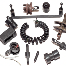
    – **Removing the Old clutch Release Bearing**
    – **Release bearing Retainer:** If there is a retainer holding the release bearing in place, remove it using appropriate tools.
    – **Extracting the Bearing:** Use the bearing puller to carefully remove the old clutch release bearing from the clutch fork or housing.

    – **Installing the New clutch Release Bearing**
    – **Preparation:** Clean the area where the new bearing will be installed to remove any debris or old lubricant.
    – **Positioning the New Bearing:** Carefully install the new clutch release bearing into the clutch fork or housing, ensuring it is seated properly.
    – **Reinstall Retainer:** If applicable, reinstall the bearing retainer to secure the new bearing in place.

    – **Reassembling the clutchdownload Terex Wheel Loader TL100 workshop manual and Transmission**
    – **Aligning the Clutch:** Use the clutch alignment tool to ensure the clutch disc is correctly aligned with the flywheel.
    – **Reinstall the Transmission:** Carefully guide the transmission back into position, ensuring all alignment pins are aligned.
    – **Bolting the Transmission:** Securely bolt the transmission back to the Engine using the specified torque values from the owner’s manual.

    – **Reconnecting Components**
    – Reattach any components that were removed previously, such as the driveshaft, exhaust system, and hydraulic lines.
    – Ensure all connections are tight and secure.

    – **Final Checks**
    – **Reconnect the Battery:** Reconnect the negative terminal of the battery.
    – **Fluid Levels:** Check and fill any necessary fluids, such as transmission fluid or hydraulic fluid.
    – **Test Operation:** Start the Terex Wheel Loader and test the clutch operation. Look for any unusual noises or issues during operation.

    – **Dispose of Old Parts Properly**
    – Ensure the old release bearing and any other discarded components are disposed of according to local regulations.

    Following these steps will help you successfully replace the clutch release bearing on a Terex Wheel Loader TL100. Always refer to the specific service manual for additional details and specifications related to your model.
    A cable release is a mechanical device commonly used in photography and certain automotive applications, designed to trigger or release a function remotely without the need for direct manual interaction with the mechanism. In photography, a cable release allows photographers to take a picture without physically touching the camera, which helps minimize camera shake and results in sharper images, especially during long exposures or when using telephoto lenses. The device typically consists of a flexible cable that connects a button or lever to the camera’s shutter mechanism. When the photographer presses the button, the cable transmits the action to the camera, releasing the shutter and capturing the image.

    In automotive contexts, a cable release can refer to a mechanism that operates a variety of functions, including hood latches, trunk releases, or even emergency brake systems. This component usually consists of a pull cable that connects a handle inside the vehicle to the latch mechanism outside. When the driver pulls the handle, it pulls on the cable, which in turn releases the latch, allowing the hood or trunk to open. The cable release system is designed for ease of use and accessibility, enabling quick access to essential components of the vehicle without the need for additional tools.

    Overall, the cable release is a simple yet effective tool that enhances functionality and user experience in both photography and automotive applications.

    Download Case 521E Parts-

    shop
    Repairing the suspension on a Case 521E involves several steps that typically need to be performed in a specific order to ensure safety and effectiveness. click here for more details on the download manual…..


      How to: Operate A Wheel Loader Quick video on how to Operate a wheel loader like I said in the video there are other switches to control functions to control things …

      Toro 521 snow blower recoil starter install and carburetor clean I purchased the snow blower for cheap and begin to diagnose it. After installing the recoil starter and cleaning the carburetor I …

    Here’s a reverse order of the suspension repair process:

    ### 7. Reassemble the Components
    – **Reattach Wheels**: If you removed the wheels, reattach them and ensure they are torqued to the manufacturer’s specifications.
    – **Reconnect any removed components**: This includes any brackets, shields, or covers that were taken off during the repair process.

    ### 6. Test the Suspension
    – **Check for proper operation**: Once everything is reassembled, operate the machine to ensure the suspension is functioning correctly. Look for any unusual noises or signs of misalignment.
    – **Inspect for leaks**: If hydraulic components were involved, check for leaks.

    ### 5. Install New Components
    – **Install new parts**: Replace any worn-out components, such as bushings, springs, or shocks, ensuring they are properly seated and secured.
    – **Torque specifications**: Use a torque wrench to tighten bolts to the manufacturer’s specifications.

    ### 4. Remove Old Components
    – **Take out damaged parts**: Carefully remove any worn or damaged suspension components. This may involve unbolting shocks, springs, or control arms.
    – **Mark and label components**: If necessary, mark the location of components for easier reinstallation.

    ### 3. Lift the Machine
    – **Use a hydraulic lift or jack**: Safely elevate the machine to access the suspension components. Make sure to use jack stands for safety.

    ### 2. Prepare the Work Area
    – **Gather tools and parts**: Ensure you have all necessary tools (wrenches, sockets, etc.) and replacement parts ready.
    – **Clean the area**: Remove any debris or obstructions from the work area to ensure a safe working environment.

    ### 1. Safety Precautions
    – **Wear safety gear**: Use gloves, goggles, and other appropriate safety equipment.
    – **Ensure stability**: Make sure the machine is on level grounddownload Case 521E Parts workshop manual and stable before starting any work.

    By following these steps in reverse, you can effectively perform a suspension repair on a Case 521E loader. Always consult the machine’s service manual for specific instructions and torque specifications related to your model.
    Carpet, as a component of an automobile’s interior, plays a crucial role in enhancing both the aesthetic appeal and functionality of the vehicle. primarily made from synthetic fibers like nylon, polyester, or polypropylene, car carpets serve several important purposes. They provide a soft, comfortable surface for passengers, enhancing the overall driving experience. The carpet helps to absorb sound, reducing noise levels inside the cabin and contributing to a quieter ride, which is particularly valuable in luxury vehicles.

    In addition to comfort and sound insulation, car carpets also contribute to safety. They are designed with anti-slip properties to help keep passengers stable while entering or exiting the vehicle. Many modern carpets include additional padding or insulation layers that not only absorb vibrations but also add thermal insulation, which helps maintain a comfortable temperature inside the vehicle.

    Moreover, car carpets are typically designed to be durable and resistant to wear and tear from daily use. They can withstand spills, dirt, and the wear from footwear, making them easier to clean and maintain. Many vehicles come equipped with removable carpet mats to provide additional protection and ease of cleaning. Overall, car carpets are an essential component that combines functionality, comfort, and aesthetics, significantly impacting the driving experience and interior ambiance.

    Download CASE CX290B Excavator Service Manual –

    books
    Tire rotation is an important maintenance task that can help extend the life of the tires on your CASE CX290B excavator. click here for more details on the download manual…..


      CASE Excavator CX290B Part Numbers & Equipment Tour Inspection | FridayParts Video Catalog CASE CX290B replacement spare part numbers lookup. Subscribe Our Channel! Easily match the right part numbers to your …

      Excavator Case CX290 leaking hydraulic cylinder. Sorry, little shaky vid.

    The following detailed description outlines the components involved in tire rotation and the steps to perform it effectively.

    ### Components Involved in Tire Rotation

    1. **Tires:**
    – **Size and Type:** The CASE CX290B typically uses large rubber tires designed for heavy-duty applications. Ensure you have the right size and type for your model (e.g., 20.5-25 or comparable).
    – **Tread Depth:** Check the tread depth before rotation to ensure they are within safe operating limits.

    2. **Wheels:**
    – **Rims:** The wheels that hold the tires in place; ensure they are free from damage, rust, or corrosion.
    – **Lug Nuts:** The fasteners securing the tires to the wheels; they must be properly torqued.

    3. **Jacks and Jack Stands:**
    – **Hydraulic Floor Jacks:** To lift the excavator safely.
    – **Jack Stands:** To provide stable support once the excavator is lifted.

    4. **Torque Wrench:**
    – To ensure that the lug nuts are tightened to the manufacturer’s specifications.

    5. **Tire Pressure Gauge:**
    – For measuring tire pressure before and after rotation.

    6. **Protective Equipment:**
    – Gloves, safety goggles, and steel-toed boots for personal protection.

    ### steps to Rotate Tires on a CASE CX290B Excavator

    1. **Preparation:**
    – **Safety First:** Before starting, park the excavator on a flat, stable surface. Engage the parking brake and turn off the engine.
    – **Gather Tools:** Collect all necessary tools and equipment, including jacks, jack stands, a torque wrench, and a tire pressure gauge.

    2. **Inspect Tires:**
    – Check the condition of all tires for wear, cracks, or punctures. Measure the tread depth and check for uneven wear patterns.

    3. **Lifting the Excavator:**
    – **Position the Jack:** Place the hydraulic jack under the designated lifting points of the excavator (refer to the operator’s manual for specific locations).
    – **Lift the Excavator:** Raise the excavator until the tires are off the ground.
    – **Secure with Jack Stands:** Once lifted, place jack stands under the machine to ensure stability. Never work under a vehicle supported only by a jack.

    4. **Removing the Tires:**
    – **Loosen Lug Nuts:** Using a tire iron, slightly loosen the lug nuts on the tires you plan to rotate. Do not completely remove them yet.
    – **Remove Lug Nuts and Tires:** Once the lug nuts are loosened, fully remove them and take off the tires. Keep the lug nuts in a safe place.

    5. **Tire Rotation Pattern:**
    – **Identify Rotation Pattern:** For excavators, a common rotation pattern is the “cross” pattern (front tires to rear, rear tires to front) or as specified in the operator’s manual.
    – **Rotate Tires:** Position the tires according to the predetermined rotation pattern.

    6. **Reinstalling Tires:**
    – **Place Tires on Rims:** Align the tires with the wheel studs and place them back on the rims.
    – **Hand Tighten Lug Nuts:** Start threading the lug nuts onto the wheel studs by hand to avoid cross-threading.
    – **Tighten Lug Nuts:** Use a torque wrench to tighten the lug nuts to the manufacturer’s specified torque (check the operator’s manual for the correct torque value). Tighten in a star pattern to ensure even pressure.

    7. **Lowering the Excavator:**
    – **Remove Jack Sdownload CASE CX290B Excavator workshop manual
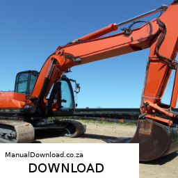
tands:** Carefully remove the jack stands.
    – **Lower the Excavator:** Slowly lower the excavator back to the ground using the hydraulic jack.

    8. **Final Checks:**
    – **Check Tire Pressure:** Use a tire pressure gauge to check and adjust each tire to the recommended pressure as specified in the operator’s manual.
    – **Inspect for Any Issues:** After rotation, inspect the tires and wheels to ensure everything is secure and in good condition.

    9. **Documentation:**
    – Log the tire rotation in the maintenance records for future reference.

    ### Conclusion

    Tire rotation on a CASE CX290B excavator is a straightforward process that can significantly improve tire longevity and performance. Following these detailed steps and safety precautions will help ensure a successful tire rotation and maintain the equipment in optimal working condition. Always refer to the operator’s manual for specific details related to your machine model.
    A tie rod end is a crucial component of a vehicle’s steering system, playing a vital role in maintaining proper alignment and steering control. It serves as a connection point between the steering knuckle and the steering rack or center link, facilitating the transfer of motion from the steering wheel to the wheels. Essentially, the tie rod end acts as a pivot point that allows the wheels to turn in accordance with the driver’s input.

    Typically made of forged steel or other durable materials, tie rod ends are designed to withstand significant forces and stresses encountered during driving. They consist of a ball joint at one end, which allows for angular movement, and a threaded shaft at the other end that connects to the steering assembly. This design enables the tie rod end to accommodate the suspension’s movement while maintaining the necessary alignment for optimal vehicle handling.

    Over time, tie rod ends can wear out due to factors like road conditions, driving habits, and exposure to environmental elements. Signs of a failing tie rod end may include uneven tire wear, steering play, or a clunking noise when turning. Regular inspection and timely replacement of worn tie rod ends are essential to ensure safe driving and maintain the overall performance of the vehicle’s steering system. Properly functioning tie rod ends contribute to precise steering response, enhanced stability, and improved tire longevity.

    Download 2016 Mercedes-Benz C63 S AMG Coupe (C205) OEM Download Service & Repair Manual Software –

    discount
    Replacing the transmission fluid sensor on a Mercedes-Benz C63 S AMG Coupe (C205) involves several steps and requires specific tools and components. click here for more details on the download manual…..


      What goes wrong with a USED Mercedes-AMG C63 S? Have peace of mind when getting a used car. Buy a Vehicle History Check now! https://bit.ly/4b94XPc This week we do a deep …

      Mercedes 2014-2019 Tip Start Remote Starter (Non Keyless Go) Now Available! Our new remote starter for non Keyless Go: 2014-2015 ML 2016-2019 GLE 2014-2015 GL 2016-2019 GLS …

    Below is a detailed guide on how to perform this replacement, including descriptions of the necessary tools and components.

    ### Tools and Equipment Needed:

    1. **OBD-II Scanner**: To check for any fault codes before and after the replacement.
    2. **Socket Set**: Metric sockets (10mm, 13mm, etc.) for removing bolts.
    3. **Torque Wrench**: To ensure bolts are tightened to factory specifications.
    4. **Screwdriver Set**: Flathead and Phillips for any clips or covers.
    5. **Pliers**: For hose clamps or electrical connectors.
    6. **Transmission Fluid**: OEM recommended fluid for your model.
    7. **Oil Drain Pan**: To catch any fluid that spills during the process.
    8. **Rags or Shop Towels**: For cleaning up any spills.
    9. **Safety Glasses and Gloves**: To protect your eyes and hands during the procedure.

    ### Components Required:

    1. **Transmission Fluid Sensor (OEM part)**: ensure you have the correct part specific to your C63 S AMG model.
    2. **Transmission Fluid**: ensure you’re using the correct type recommended by Mercedes-Benz.
    3. **Gasket or Sealing Ring**: If applicable, some sensors may require a new seal to prevent leaks.

    ### Replacement Procedure:

    #### Step 1: Safety First
    – **Disconnect the Battery**: Before starting, disconnect the negative terminal of the battery to avoid any electrical shorts or issues.

    #### Step 2: Prepare the Vehicle
    – **Lift the Vehicle**: Use a hydraulic jack to lift the front of the vehicle and secure it on jack stands. ensure it is stable before working underneath.
    – **Drain Transmission Fluid**: Place an oil drain pan under the transmission pan. Remove the transmission pan drain plug (if equipped) or remove the pan to drain the fluid completely. Make sure you have enough containers to collect all the fluid.

    #### Step 3: Locate the Transmission Fluid Sensor
    – The transmission fluid sensor is typically located on the side of the transmission or near the transmission pan. Refer to your vehicle’s service manual for the exact location, as it may vary.

    #### Step 4: Remove the Old Sensor
    – **Disconnect Electrical Connector**: Locate the electrical connector for the sensor. Press the tab and gently pull it off to disconnect.
    – **Remove mounting Bolts**: Using the appropriate socket, remove the bolts securing the sensor to the transmission. Be cautious as some fluid may still leak out.
    – **Carefully Pull Out the Sensor**: Once the bolts are removed, gently pull the sensor out of its housing. You may need to wiggle it slightly to free it.

    #### Step 5: Install the New Sensor
    – **Prepare the New Sensor**: If your new sensor came with a new sealing ring or gasket, ensure that it is installed correctly.
    – **Insert the New Sensor**: Align the new sensor with the mounting hole and insert it into place.
    – **Secure with Bolts**: Replace the mounting bolts and tighten them to the manufacturer’s specifications using a torque wrench.

    #### Step 6: Reconnect Electrical Connector
    – **Reconnect the Sensor**: Push the electrical connector back onto the new sensor until you hear a click, indicating it is securely connected.

    #### Step 7: Refill Transmission Fluid
    – **Replace the Transmission Pan**: If you removed the pan, reinstall it with a new gasket (if needed)download Mercedes Benz C63 S AMG Coupe C205 OEM workshop manual and tighten the bolts to specification.
    – **Refill Transmission Fluid**: Use the dipstick or fill port to add the new transmission fluid. Check the level according to the manufacturer’s specifications.

    #### Step 8: Test the System
    – **Reconnect the Battery**: Reattach the negative terminal of the battery.
    – **Start the Engine**: Allow it to idle for a few minutes and then shift through all gears with your foot on the brake to circulate the fluid.
    – **Check for Leaks**: Inspect the sensor area and the transmission pan for any leaks.
    – **Use an OBD-II Scanner**: Check for any fault codes related to the transmission and clear them if necessary.

    #### Step 9: Lower the Vehicle
    – Once everything is checked and looks good, lower the vehicle carefully from the jack stands and remove the jack.

    ### Conclusion
    Replacing the transmission fluid sensor on a Mercedes-Benz C63 S AMG Coupe involves careful attention to detail and adherence to safety protocols. It’s essential to use the right parts and tools, and ensure everything is reassembled correctly to avoid future issues. Always refer to the Mercedes-Benz service manual for specific details related to your vehicle model. If you’re unsure about any step, consider consulting with a professional mechanic.
    The oil drain gasket, also known as the oil pan gasket or oil drain plug gasket, is a crucial component in an automobile’s lubrication system. It serves as a seal between the oil pan and the engine block, preventing oil leaks from occurring at the drain plug area. typically made from materials such as rubber, silicone, or cork, the oil drain gasket is designed to withstand high temperatures and the corrosive nature of engine oil.

    When an engine operates, it generates a significant amount of heat, which can cause materials to expand and contract. The oil drain gasket must maintain a tight seal despite these changes to ensure that oil remains within the engine and does not leak onto the ground or into other engine components. A compromised gasket can lead to various issues, including reduced oil levels, which can result in engine wear or even catastrophic failure if not addressed promptly.

    Regularly checking the condition of the oil drain gasket is essential, especially during oil changes. Signs of wear, such as cracks, tears, or hardening, indicate that it may need replacement. Additionally, improper installation can lead to leaks; therefore, it is crucial to ensure that the gasket is installed correctly and that the oil drain plug is tightened to the manufacturer’s specifications. Overall, the oil drain gasket plays a significant role in the overall health and efficiency of an engine.

    Download 1996 Renault Master I Service and Repair Manual –

    online
    Replacing the input shaft bearing on a Renault Master I can be a complex job that requires mechanical knowledge and skills. click here for more details on the download manual…..


      Work Vanlife Renault Master Upgrade DMX7722DABS CarPlay, Android Auto Renault Master Van get Wireless Apple CarPlay and Android Auto in your van? Check out this car audio installation by Boundary …

      Used 2020 – Renault Master | Used Truck with 4×2 axle | equippo.com | Used heavy equipment EQUIPPO. The easiest way to buy used equipment For more information on this machine visit: …

    Below is a detailed step-by-step guide to help you through the process. Please ensure you have the necessary tools and safety equipment before starting.

    ### Tools and Materials Needed:

    1. **Tools:**
    – Socket set (including deep sockets)
    – Wrench set
    – Torque wrench
    – Screwdrivers (flathead and Phillips)
    – Pliers
    – Hammer
    – Bearing puller
    – Gear puller (if needed)
    – Pry bar
    – Jack and jack stands
    lubricant (grease)
    cleaning materials (brake cleaner, rags)

    2. **Replacement Parts:**
    – Input shaft bearing
    – Seals (if applicable)
    – Additional gaskets (if required)

    ### Step-by-Step Procedure:

    #### 1. Preparation
    – **Safety First:** Ensure you are wearing appropriate safety gear, including gloves and goggles.
    – **Workspace:** Work in a well-ventilated area with sufficient lighting.
    – **Vehicle Position:** Park the Renault Master on a flat surface and engage the parking brake.

    #### 2. Remove the Gearbox
    – **Disconnect the Battery:** Remove the negative terminal from the battery to prevent any electrical issues.
    – **Lift the Vehicle:** Use a jack to raise the vehicle and secure it with jack stands.
    – **Remove the Gear Shifter:** depending on the model, you may need to remove the gear shifter to access the gearbox.
    – **Drain Transmission Fluid:** Place a container underneath the gearbox and drain the fluid to avoid spills.
    – **Disconnect Driveshafts:** Unbolt the driveshafts from the gearbox and the rear differential. Use a pry bar if necessary to separate them.
    – **Support the Gearbox:** Use a transmission jack or a suitable support to hold the gearbox in place.
    – **Remove Mounting Bolts:** Unbolt the gearbox from the engine and any supporting brackets. These are typically located on the sides and bottom of the gearbox.
    – **Carefully Remove Gearbox:** Lower the gearbox from the engine, ensuring that all connections (wires, sensors) are disconnected.

    #### 3. Accessing the Input Shaft Bearing
    – **Inspect the Gearbox:** Once the gearbox is out, inspect it for any other potential issues.
    – **Remove the Gearbox Cover:** Unbolt the cover that protects the input shaft area. This will expose the input shaft and the bearing.
    – **Remove the Input Shaft:** depending on the design, you may need to remove the clutch assembly and any retaining clips or bolts securing the input shaft in place. Use a bearing puller if the shaft is stuck.

    #### 4. Bearing Replacement
    – **Remove the Old Bearing:** Using a bearing puller, carefully extract the old input shaft bearing from its housing. Take care not to damage the bearing housing.
    – **Clean the Area:** Use brake cleaner to thoroughly clean the bearing housing and surrounding areas. Ensure no debris remains.
    – **Install the New Bearing:** Apply a thin layer of grease to the new bearing and gently press it into place using a bearing installer tool or a soft hammer (if applicable). Ensure it sits flush and correctly aligned.

    #### 5. Reassemble the Gearbox
    – **Reinstall Input Shaft:** Insert the input shaft back into place, ensuring it is securedownload Renault Master I workshop manual and correctly aligned.
    – **Replace the Gearbox Cover:** Bolt the cover back onto the gearbox, ensuring all bolts are tightened to the manufacturer’s specifications.
    – **Reinstall the Clutch Assembly:** If removed, reinstall the clutch assembly, ensuring proper alignment.

    #### 6. Reattach the Gearbox
    – **Lift Gearbox Back into Place:** Carefully lift the gearbox back into position on the engine, using a transmission jack.
    – **Bolt the Gearbox:** Secure the gearbox to the engine with the previously removed bolts, ensuring they are torqued to the manufacturer’s specifications.
    – **Reconnect Driveshafts:** Reattach the driveshafts to the gearbox and rear differential, ensuring all bolts are tightened.
    – **Reconnect the Gear Shifter:** If removed, reinstall the gear shifter.

    #### 7. Final Steps
    – **Refill Transmission Fluid:** Refill the gearbox with the appropriate transmission fluid.
    – **Reconnect the Battery:** Reattach the negative terminal of the battery.
    – **Check for Leaks:** Start the engine and check for any fluid leaks around the gearbox and input shaft area.
    – **Test Drive:** Take the vehicle for a short test drive to ensure everything is functioning correctly.

    ### Conclusion

    Replacing the input shaft bearing on a Renault Master I involves careful disassembly and reassembly of the gearbox. Always refer to the manufacturer’s service manual for specific torque settings and additional details. If you are unsure about any steps or lack experience, consider seeking assistance from a professional mechanic.
    The timing cover is a crucial component of an internal combustion engine, serving as a protective casing for the timing mechanisms that synchronize the rotation of the crankshaft and camshaft. Typically made of metal or durable plastic, the timing cover is located at the front of the engine, sealing the timing belt or chain, as well as the gears and pulleys that control the timing of the engine’s valves.

    One of the primary functions of the timing cover is to prevent contaminants such as dirt, dust, and oil from entering the timing components, which could lead to premature wear or failure. Additionally, the cover helps retain lubricating oil within the timing area, ensuring that the gears and chains remain adequately lubricated for smooth operation. It also plays a role in maintaining the engine’s overall structural integrity and aligning other components like the water pump and oil pump.

    In many cases, the timing cover includes access points for maintenance, allowing mechanics to inspect or replace timing belts and chains without needing to disassemble the entire engine. Over time, timing covers can develop leaks, particularly due to wear and tear on seals and gaskets. Regular inspection is essential, as a compromised timing cover can lead to oil leaks, engine overheating, and potential engine damage if not addressed promptly. Overall, the timing cover is an integral component that contributes significantly to the reliability and longevity of an engine.

    Download BMW 5 Series 518 1985 1986 1987 1988 Workshop Service Manual –

    workshop
    Cleaning fuel injectors in a BMW 518 (or similar vehicles) can help improve engine performance, fuel efficiency, and reduce emissions. click here for more details on the download manual…..


      F10 BMW 518d 2.0 Diesel (Engine Code – N47D20O1) 21,497 Miles

      Night ride bmw 518d e61 #bmw #bmwtech #bmwgermany #exhaust #bmwgroup

    If you’re not mechanically experienced, it’s best to approach this task carefully or consider having a professional do it. However, if you’re interested in understanding the Basic process, here’s a simplified explanation.

    ### What You’ll Need:
    1. **Fuel injector Cleaning Kit**: This can be bought online or at an auto parts store. It usually includes a cleaning solution, a pressure gauge, and adapters for your fuel rail.
    2. **Safety Gear**: Gloves and safety glasses to protect yourself.
    3. **Basic Tools**: A socket set, wrenches, and possibly a screwdriver.
    4. **Shop Towels**: To clean up any spills.
    5. **Fuel**: Additional fuel might be needed for testing after cleaning.

    ### Steps to Clean fuel Injectors:

    1. **Safety First**:
    – Ensure the vehicle is parked on a flat surface, and the engine is off and cool.
    – Disconnect the battery to avoid any electrical issues.

    2. **Locate the fuel Injectors**:
    – Open the hood and locate the fuel rail where the injectors are installed. This is usually found near the intake manifold.

    3. **Remove the Engine Cover** (if applicable):
    – Some BMW models have a plastic cover over the engine that may need to be removed. Use the appropriate tools to take it off.

    4. **Disconnect the fuel Injectors**:
    – Carefully unplug the electrical connectors from the fuel injectors. You may need to press on a tab or use a small screwdriver to release them.

    5. **Relieve fuel Pressure**:
    – Before removing any fuel-related components, it’s crucial to relieve fuel pressure. This can usually be done by removing the fuel pump fuse and starting the engine until it stalls.

    6. **Remove the fuel Rail**:
    – Depending on your model, you may need to unbolt the fuel rail from the engine. Be cautious as fuel may still be present. Have shop towels ready to catch any spills.

    7. **Attach the Cleaning Kit**:
    – Follow the instructions provided with your cleaning kit. Typically, you’ll attach the cleaning solution canister to the fuel rail where the injectors were connected.

    8. **Flush the Injectors**:
    – Start the cleaning solution flow by following the instructions on your kit. This usually involves running the engine (if possible) or pressurizing the cleaning solution through the injectors. The cleaning solution will help remove depositsdownload BMW 5 518 workshop manual and clean the injectors.

    9. **Reassemble Everything**:
    – After the cleaning is complete, carefully remove the cleaning kit and reattach the fuel rail and injectors. Make sure everything is secure and the electrical connectors are plugged back in.

    10. **Reconnect the Battery**:
    – Once everything is back in place, reconnect the battery.

    11. **Test the Vehicle**:
    – Start the engine and let it run for a few minutes to ensure everything is functioning correctly. Check for any leaks or unusual sounds.

    12. **Dispose of Cleaning Solution**:
    – Follow local regulations for disposing of any waste or leftover cleaning solution.

    ### Final Tips:
    – If you’re unsure at any step, consult a repair manual specific to your vehicle or seek assistance from a professional mechanic.
    – Regular maintenance, including fuel injector cleaning, can help extend the life of your engine and improve performance.

    Remember, while this guide provides a Basic overview, working on a vehicle can be complex, and safety should always be your top priority. If you’re not comfortable with any steps, it’s best to leave the job to a professional.
    The master cylinder is a crucial component of a vehicle’s hydraulic brake system, playing a vital role in ensuring effective braking performance. It serves as the primary source of hydraulic pressure, converting the mechanical force applied by the driver’s foot on the brake pedal into hydraulic pressure that operates the brake calipers or wheel cylinders at each wheel.

    Typically made from aluminum or cast iron, the master cylinder houses one or more pistons, which move within a cylindrical chamber. When the brake pedal is pressed, the piston is pushed forward, compressing brake fluid in the chamber. This action creates hydraulic pressure that is transmitted through brake lines to the brake components at each wheel. Most modern vehicles utilize a dual master cylinder design, which enhances safety by providing redundancy. If one circuit fails, the other can still function, allowing for partial braking ability.

    The master cylinder contains several key features, including a reservoir for brake fluid, ensuring a consistent supply for hydraulic operation. It also incorporates seals and O-rings to prevent fluid leaks, which could compromise braking efficiency. Regular inspection and maintenance of the master cylinder are essential, as issues such as fluid contamination or air in the system can lead to decreased braking performance, potentially compromising vehicle safety. Overall, the master cylinder is an integral part of the braking system, directly influencing a vehicle’s ability to stop effectively and safely.

    Download Mitsubishi Eclipse 2000 Factory Service Repair Manual –

    online
    Repairing a Transmission Control Module (TCM) on a Mitsubishi Eclipse involves several steps. click here for more details on the download manual…..


      UPGRADE YOUR DSM COOLANT HOSES WITH SILICONE REINFORCED HOSES! -(2G DSM) hi everyone! in this episode i will show you how i installed my new high temp-reinforced-silicone radiator and water line kit! here is …

      The FASTEST 4 Cyl TURBO Car Ever Made #mitsubishi #eclipse The FASTEST 4 Cyl TURBO Car Ever Made #mitsubishi #eclipse.

    Here’s a reverse order guide to help you understand the process:

    ### step 10: Reassemble
    – Ensure all components are reinstalled in reverse order of removal.
    – Reconnect the battery and any electrical connectors that were disconnected.

    ### step 9: Test Drive
    – After reassembly, perform a test drive to ensure that the TCM is functioning correctly and that there are no issues with shifting or transmission performance.

    ### step 8: Reconnect Electrical Connectors
    – Reconnect all electrical connectors to the TCM and ensure they are securely fastened.

    ### step 7: Install the TCM
    – Carefully place the repaired or replaced TCM back into its designated location.
    – Secure it using the bolts or screws removed earlier.

    ### step 6: Inspect and Repair the TCM (if necessary)
    – If the TCM is repairable, identify and fix any issues (such as solder joints, damaged components, etc.).
    – If the TCM is beyond repair, install a new or refurbished unit.

    ### step 5: Remove the TCM
    – Disconnect the battery to prevent any electrical shorts.
    – Locate the TCM, which is typically found near the transmission or under the dashboard.
    – Remove any screws or bolts that secure the TCM in place, and gently disconnect the wiring harness.

    ### step 4: Diagnose the Problem
    – Use a diagnostic tool to check for any error codes related to the transmission.
    – Identify if the issue is with the TCM itself or if there are other related issues (like wiring or sensor problems).

    ### step 3: Gather Tools and Parts
    – Gather necessary tools (screwdrivers, socket set, multimeter, etc.) and any replacement parts needed for the repair.

    ### step 2: Prepare the Vehicle
    – Park the vehicle on a level surface, engage the parking brake,download Mitsubishi Eclipse workshop manual and ensure the engine is off before starting the repair.

    ### step 1: Safety Precautions
    – Wear safety goggles and gloves to protect yourself during the repair process.

    By following these steps in reverse order, you can systematically approach the repair of the Transmission Control Module on a Mitsubishi Eclipse. Always refer to the vehicle’s service manual for specific instructions and torque specifications related to your model year.
    A seat cover is an essential automotive accessory designed to protect and enhance the seats of a vehicle. It serves multiple purposes, primarily focusing on safeguarding the original upholstery from wear and tear, stains, and damage caused by spills, pets, or daily use. Seat covers can be made from various materials, including fabric, leather, neoprene, and vinyl, each offering different levels of comfort, durability, and aesthetic appeal.

    One of the key benefits of seat covers is their ability to personalize the interior of a vehicle. Available in a wide range of colors, patterns, and styles, seat covers allow car owners to express their individuality and match their vehicle’s interior to their personal taste. Additionally, many seat covers are designed with extra padding or ergonomic features, enhancing comfort during long drives.

    Installation of seat covers is typically straightforward, with many products designed for easy fitting over existing seats. Some covers are custom-fit for specific vehicle models, ensuring a snug fit that doesn’t interfere with seat functionality, including airbags and seat adjustments. Moreover, seat covers are often machine washable, making maintenance convenient.

    In summary, seat covers are a practical solution for protecting car seats while also providing an opportunity for customization and improved comfort, making them a popular choice among vehicle owners.

    Download 1971-1974 Jaguar E-type Series Iii V12 Parts Workshop Service Repair Manual –

    buy
    Overhauling the gear set on a Jaguar E-Type Series III V12 is a complex task that requires mechanical expertise. click here for more details on the download manual…..


      Test Drive – 1973 Jaguar E-Type Series III V12 Coupe! This is a stunning 1973 Jaguar XKE Coupe that has been in California and Arizona with a mere 40600 miles travelled since new.

      Jaguar E-type series 3 V12 straight piped ! 5 speed tremec conversion . Friends resto mod straight piped v12 series 3 , 2 plus 2 E-type RHD.. fully built engine .. I drove this car and it really does sound …

    Below is a reverse order guide to help you understand the steps involved in this process. Please make sure to follow safety precautions and consult a service manual for detailed specifications and torque settings.

    ### 6. Reassemble the Differential
    – **Install the Differential Cover**: Use a new gasket and torque bolts to the specified settings.
    – **Reattach the Driveshaft**: Align the driveshaft with the differential and secure it.
    – **Reinstall the Brake Hubs and Wheels**: Put the brake components back in place and torque the wheel nuts.

    ### 5. Final Adjustments
    – **Check Gear Mesh**: Verify the gear mesh pattern using a marking compound.
    – **Set Backlash**: Measure the backlash and adjust as necessary by modifying shims.
    – **Lubricate**: Fill the differential with the appropriate gear oil.

    ### 4. Install the Ring and Pinion
    – **Install the Pinion Gear**: Place the pinion gear into the housing, ensuring the proper preload is set with shims.
    – **Install the Ring Gear**: Attach the ring gear to the differential casing, ensuring proper alignment with the pinion.
    – **Check Preload and Backlash**: Ensure both are set to manufacturer specifications.

    ### 3. Rebuild the Differential Assembly
    – **Disassemble the Differential**: Remove the old bearings and seals from the differential case.
    – **Replace Bearings**: Install new bearings and seals, ensuring they are properly seated.
    – **Install the Spider Gears**: Reassemble the differential with new spider gears if necessary.

    ### 2. Remove the Old Gear Set
    – **Remove the Differential from the Car**: Disconnect the suspension components and remove the differential from the vehicle.
    – **Disassemble the Differential**: Take apart the differential to access the ring and pinion gear set.

    ### 1. Preparation and Safety
    – **Gather Tools and Parts**: Ensure you have all necessary tools (socket set, torque wrench, bearing puller, etc.) and replacement parts.
    – **Safety Precautions**: Wear safety glasses and gloves. Make sure the vehicle is securely supported on jack stands.

    ### Additional Considerations
    – **Documentation**: Keep a detailed record of all settings and adjustments made during the process.
    – **Consult the Manual**: Refer to the Jaguar service manual for specific torque values and part numbers.
    – **Test Drive**: After reassembly, perform a test drive to ensure everything is functioning correctly.

    This reverse order guide provides a framework for overhauling the gear set on a Jaguar E-Type Series III V12. However, it is essential to have a comprehensive undersdownload Jaguar E type Iii V12 workshop manualtanding of the vehicle and its components before attempting such a task.
    The mass airflow sensor (MAF sensor) is a critical component in modern internal combustion engines, playing a vital role in the vehicle’s engine management system. It is responsible for measuring the amount of air entering the engine, which is essential for the engine control unit (ECU) to calculate the appropriate fuel injection needed for optimal combustion. This precise measurement ensures that the engine operates efficiently, maximizes power output, and minimizes emissions.

    Typically located in the intake system, between the air filter and the throttle body, the MAF sensor can come in various designs, most commonly as a hot Wire or a vane type. In a hot Wire MAF sensor, a thin Wire is heated to a specific temperature, and as air flows over it, the Wire cools down. The ECU measures the amount of current required to maintain the wire’s temperature, which correlates to the mass of the incoming air. Vane-type sensors use a movable vane that deflects according to the airflow, providing a mechanical measurement of air volume.

    A malfunctioning MAF sensor can lead to a host of engine performance issues, including poor fuel economy, rough idling, stalling, and increased emissions. Common symptoms of a faulty MAF sensor include a check engine light, hesitation during acceleration, and difficulty starting the engine. Regular maintenance and timely replacement of this component are crucial for ensuring the smooth operation of the vehicle’s engine.

    Download Komatsu PC1250-8 manual collection. 4 x manuals –

    service manual
    Repairing the suspension knuckle on a Komatsu PC1250-8 involves a series of detailed steps. click here for more details on the download manual…..

        Here’s a reverse order breakdown of the process, assuming you have access to the necessary manuals for specific torque specifications and detailed diagrams.

        ### 8. Final Assembly
        1. **Reinstall the Wheel Hub**: Attach the wheel hub to the suspension knuckle and secure it with bolts, ensuring they are torqued to the manufacturer’s specifications.
        2. **Reconnect the Brake Components**: If the brake system was removed, reinstall it according to the service manual.
        3. **Install New Seals and Gaskets**: Ensure that all new seals and gaskets are properly fitted to prevent leaks.

        ### 7. Suspension Knuckle Installation
        1. **Position the Knuckle**: Carefully align the suspension knuckle with the axle housing.
        2. **Secure the Knuckle**: Use the appropriate bolts to secure the knuckle, following the recommended torque settings.

        ### 6. Bearing and Seal Replacement
        1. **Install Bearings**: If bearings were replaced, ensure they are seated properly in the knuckle.
        2. **Replace Seals**: install new seals to prevent oil leaks.

        ### 5. Disassembly of the Suspension Knuckle
        1. **Remove the Knuckle**: Detach the suspension knuckle from the axle housing by removing the mounting bolts.
        2. **Take Out Bearings and Seals**: remove any bearings and seals from the knuckle for inspection or replacement.

        ### 4. Inspect Components
        1. **Check for Damage**: Inspect the knuckle, bearings, seals, and other related components for wear or damage.
        2. **Clean Parts**: Thoroughly clean all parts to be reused to remove dirt and debris.

        ### 3. Preparation for Repair
        1. **Gather Tools and Parts**: Collect all the necessary tools, replacement parts, and manuals.
        2. **Ensure Safety**: Use proper safety gear and ensure the work area is clear.

        ### 2. Diagnosis of the Issue
        1. **Identify Symptoms**: Confirm that the suspension knuckle is the source of the problem (e.g., unusual noises, play in the wheel).
        2. **Consult Manuals**: Refer to the service manuals for troubleshooting guidelines specific to the Komatsu PC1250-8.

        ### 1. Safety Precautions
        1. **Park the Equipment**: Ensure that the Komatsu PC1250-8 is parked on a flat surface.
        2. **Engage the Parking Brake**: Engage the parking brake to prevent movement.
        3. **Disconnect the Battery**: Disconnect the battery to ensure safety while working on electrical components.

        ### Conclusion
        Following these reverse order steps will help in successfully repairing the suspension knuckle of a Komatsu PC1250-8. Always refer to the specific service manuals for detailed procedures, torque specifications,download Komatsu PC1250 8. 4 x manuals workshop manual and safety instructions.
        A CD player, or compact disc player, is an electronic device designed to read and play audio CDs, which store digital audio data on optical discs. This component became a standard feature in vehicles starting in the late 1980s and throughout the 1990s and early 2000s, serving as a primary source of music for many drivers and passengers.

        The CD player consists of several key components: a laser assembly, a spindle motor, and a digital-to-analog converter (DAC). The laser assembly reads the disc’s encoded data by shining a laser onto the surface of the CD, which is a reflective medium. The information is stored in the form of tiny pits and lands that represent binary data. As the disc spins, the laser detects these variations and converts them into audio signals through the DAC, allowing the sound to be amplified and played through the vehicle’s speakers.

        Despite the rise of digital streaming services and portable music players, which have increasingly diminished the popularity of physical media, many car manufacturers still include CD players in their audio systems, catering to consumers who appreciate the tactile experience of handling CDs or who have extensive physical music collections. However, as technology continues to evolve, the relevance of CD players is waning, with many newer car models forgoing them in favor of more modern connectivity options like Bluetooth and USB ports. Nonetheless, the CD player remains a nostalgic component for many, symbolizing a significant era in automotive audio technology.

        Download 2010 Audi R8 GT Download Service & Repair Manual –

        books
        Replacing the upper control arm on an Audi R8 GT is a complex procedure that requires mechanical knowledge, the right tools, and safety precautions. click here for more details on the download manual…..


          Cost To Own An Audi R8 V10 #shorts #audir8 #automobile

          Twin Turbo V10 Audi R8 Dyno Run with Switchable Burble and Flame Mode Get a glimpse of this customer’s one-of-a-kind Audi R8 as it undergoes some serious tuning on the dyno. This V10 beast has been …

        Below is a comprehensive guide to help you through the process. Note that this is a generalized description, and specific steps may vary depending on the model year and specific configuration of your R8 GT.

        ### Tools and Materials Needed

        1. **Tools:**
        – Floor jack
        – Jack stands
        – Torque wrench
        – Socket set (including deep sockets)
        – Ratchet and extensions
        – Wrenches (including adjustable)
        – Pliers
        – Hammer or mallet
        – Pry bar
        – Screwdrivers (flat and Phillips)
        – Allen wrenches (if necessary)
        – Ball joint separator (optional, but helpful)

        2. **Replacement Parts:**
        – New upper control arm (OEM or aftermarket)
        – New bushings (if not included with the control arm)
        – New ball joint (if applicable)
        – New bolts and nuts (recommended to use OEM)

        3. **Safety Equipment:**
        – Safety glasses
        – Gloves
        – Mechanic’s creeper (optional)

        ### Procedure

        #### Step 1: Preparation and Safety

        1. **Park on a Level Surface:**
        ensure the vehicle is parked on a flat, stable surface, and engage the parking brake.

        2. **Gather Tools:**
        – Collect all the necessary tools and parts before starting the job.

        3. **Safety Gear:**
        – Put on safety glasses and gloves to protect yourself.

        #### Step 2: Lift the Vehicle

        1. **Loosen Lug Nuts:**
        – Before lifting the vehicle, slightly loosen the lug nuts on the front wheels using a lug wrench.

        2. **Jack Up the Vehicle:**
        – Use a floor jack to lift the front of the vehicle. Place jack stands under the vehicle’s frame for support.

        3. **Remove Front Wheels:**
        – Once the vehicle is securely lifted and supported, remove the lug nuts completely and take off the front wheels.

        #### Step 3: Access the Upper control Arm

        1. **Locate the Upper control Arm:**
        – The upper control arm is connected to the top of the wheel hub assembly and the chassis.

        2. **Remove any Obstructions:**
        – Depending on the model, you may need to remove additional components such as the wheel well liner or brake components to access the control arm.

        #### Step 4: Remove the Upper control Arm

        1. **Disconnect the Ball Joint:**
        – If the upper control arm has a ball joint, use a ball joint separator or a hammer to disconnect it from the wheel hub assembly. Be cautious to avoid damaging the ball joint if you plan to reuse it.

        2. **Remove bolts and Nuts:**
        – Locate the bolts securing the upper control arm to the chassis. Use the appropriate socket or wrench to remove these bolts. Keep track of any washers or spacers.

        3. **Remove the control Arm:**
        – Carefully pull the upper control arm out of its mounting points. If it is stuck, use a pry bar gently to assist in removal.

        #### Step 5: Install the New Upper control Arm

        1. **Prepare New control Arm:**
        – Compare the new control arm to the old one to ensure it is the correct part. If the new control arm has bushings or a ball joint, ensure they are properly installed.

        2. **Position New control Arm:**
        – Align the new upper control arm into its mounting position on the chassis.

        3. **Insert bolts and nuts to secure the control arm in place. Don’t fully tighten them yet.

        4. **Reconnect Ball Joint:**
        – If you removed the ball joint, reattach it to the wheel hub assembly. ensure it is seated correctly and tighten the nut securely.

        #### Step 6: Final Tightening and Reassembly

        1. **Torque Specifications:**
        – Using a torque wrench, tighten all bolts and nuts to the manufacturer’s specified torque settings. Consult your service manual for the exact torque values.

        2. **Reattach Any Removed Components:**
        – Reinstall any components that were removed during the process, such as brake components or wheel well liners.

        3. **Reinstall Front Wheels:**
        – Place the front wheels back onto the wheel hubs, hand-tightening the lug nuts.

        4. **Lower the Vehicle:**
        – Carefully lower the vehicle back to the ground using the floor jack, then remove the jack stands.

        5. **Tighten Lug Nuts:**
        – Once the vehicle is on the ground, use a torque wrench to tighten the lug nuts to the specified torque setting in a crisscross pattern.

        #### Step 7: Final Checks

        1. **Inspect Work:**
        – Double-check all connections and ensure everything is properly secured.

        2. **Test Drive:**
        – Take the vehicle for a short test drive to ensure proper handling and listen for any unusual noises.

        3. **Alignment:**
        – After replacing suspension components, it is advisable to have a professional wheel alignment performed to ensure proper handling and tire wear.

        ### Conclusion

        Replacing an upper control arm on an Audi R8 GT requires precision and attention to detail. Always refer to the vehicle’s service manual for specific instructions and torque specifications. If you are not confident in your abilities, consider seeking professional assistance.
        The blower motor is a critical component of a vehicle’s heating, ventilation, and air conditioning (HVAC) system. Its primary function is to circulate air within the cabin, ensuring that passengers remain comfortable regardless of external weather conditions. The blower motor is typically located inside the dashboard or under the hood, depending on the vehicle’s design, and it works in conjunction with the HVAC controls to deliver heated or cooled air to the interior of the vehicle.

        When the driver or passengers adjust the temperature settings, the blower motor responds by turning on and varying its speed, allowing for precise control over airflow. This component is essential not only for climate control but also for defrosting and defogging the windows, enhancing visibility and safety while driving. The blower motor usually features a fan that can operate at multiple speeds, and it is powered by the vehicle’s electrical system.

        Over time, blower motors can experience wear and tear, leading to issues such as reduced airflow, strange noises, or complete failure to operate. Regular maintenance can help ensure its longevity, but if problems arise, it may need to be inspected or replaced. Overall, the blower motor plays a vital role in passenger comfort and safety, making it an essential part of any vehicle’s HVAC system.