Download Subaru Forester 2005 Factory Service Repair Manual –

service manual
Certainly! click here for more details on the download manual…..


    Subaru Forester Wilderness Off-Road Mud and Rock Test We hit the hard lines our new Peninsula Off-Road Course. Can the new Subaru Forester Wilderness rise to the occasion?

    All-New Subaru Forester Review Shop for a new Subaru Forester on CarGurus: https://cargur.us/13dHXf We’re out here in Montana at a Subaru Drive program, …

Here’s a reverse order guide to replacing the fuel pump on a Subaru Forester. This means we will start from the last step and work our way back to the first:

### Step 10: Reconnect the Battery
Reconnect the negative battery terminal and ensure it is tight.

### Step 9: Reassemble the Components
If you removed any other components, such as a cover or the rear seat cushion, reinstall them now.
– Make sure all screws, bolts, and clips are securely fastened.

### Step 8: Reattach the Fuel Lines and electrical Connectors
Reconnect the fuel lines to the pump assembly, ensuring they are secure.
– Plug in any electrical connectors related to the fuel pump.

### Step 7: Install the New Fuel Pump
– Carefully lower the new fuel pump assembly into the fuel tank, aligning it properly.
– Secure the assembly with the retaining ring or screws as per the manufacturer’s specifications.

### Step 6: Remove the Old Fuel Pump
– Disconnect the electrical connector and the fuel lines from the old pump.
– Remove the retaining ring or screws holding the old pump in place and take it out of the tank.

### Step 5: Access the Fuel Pump
If necessary, remove the rear seat cushion to access the fuel pump access panel.
– Unscrew the access panel and set it aside to expose the fuel pump assembly.

### Step 4: Relieve Fuel System Pressure
– Locate the fuel pump fuse in the fuse box and remove it.
– Start the engine until it stalls to relieve pressure in the fuel system.
– Turn the ignition off and wait for a few minutes.

### Step 3: Gather Tools and Equipment
– Gather necessary tools: screwdrivers, pliers, socket set, fuel line disconnect tool, and safety goggles.
– Have the replacement fuel pump and any necessary gaskets or O-rings ready.

### Step 2: Safety Precautions
– Ensure you are working in a well-ventilated area and away from open flames.
– Wear safety goggles and gloves to protect yourself from fuel splashes.

### Step 1: Prepare the Vehicle
– Park the vehicle on a level surfacedownload Subaru Forester workshop manual and turn off the ignition.

– Disconnect the negative battery terminal to prevent any electrical shorts.

By following these steps in reverse order, you can successfully replace the fuel pump on a Subaru Forester. Remember to consult a service manual for specific details related to the model year of your vehicle, as procedures may vary slightly.
An oil cooler is a critical component in many automotive and industrial applications, designed to regulate the temperature of engine oil, ensuring optimal performance and longevity of the engine. It functions by dissipating the heat generated from the engine oil during operation, which can become excessively hot due to friction, combustion byproducts, and the general demands of high-performance driving.

Typically, an oil cooler resembles a small radiator and is usually mounted in front of the vehicle’s main radiator or in a location where airflow can effectively cool the oil. The design often includes a series of tubes and fins that maximize the surface area for heat exchange. As the hot oil circulates through these tubes, air flows over the fins, transferring heat away from the oil and allowing it to return to a cooler temperature before re-entering the engine.

The benefits of an oil cooler are significant. By keeping the oil at a stable and lower temperature, it enhances the lubricating properties of the oil, reducing wear on engine components, improving fuel efficiency, and preventing thermal breakdown of the oil. This is particularly vital in performance vehicles, towing applications, or environments where the engine operates under heavy loads or extreme conditions. In summary, an oil cooler is an essential component for maintaining engine health, enhancing performance, and prolonging the lifespan of the engine.

Download 2005 Mazda MPV Service & Repair Manual Software –

bookstore
Replacing the anti-roll bar (also known as a sway bar) on a Mazda MPV involves several steps. click here for more details on the download manual…..


    Rear Wheel bearing replacement for Mazda mpv Basically an easy repair in replacing the rear wheel bearing I. The Mazda mpv with drum brakes.

    Rear Air Shock Replacement 1997 Mazda Mpv Rear air shock replacement. Very easy only have to remove two bolts and properly support the car.

below is a reverse order guide to help you understand the process.

### 7. Final Checks
– **Inspect the Installation:** Ensure that all bolts and nuts are tightened to the specified torque.
– **Check for Clearance:** Ensure there is adequate clearance between the anti-roll bar and other components.
– **Test Drive:** Take the vehicle for a short test drive to check for any unusual noises or handling issues.

### 6. Reinstall the Wheel
– **Place the Wheel Back:** Align the wheel with the hub and push it into place.
– **Secure the lug Nuts:** Hand-tighten the lug nuts, and then lower the vehicle slightly to torque them to the manufacturer’s specifications.

### 5. Lower the Vehicle
– **Use a Jack:** Carefully lower the vehicle back to the ground using a jack.

### 4. Remove the old Anti-Roll Bar
– **Detach from Linkage:** Remove the end links that connect the anti-roll bar to the suspension components.
– **Unbolt the Bar:** Remove bolts securing the anti-roll bar to the chassis. There may be brackets holding it in place that should also be removed.
– **Take Out the Bar:** Carefully maneuver the old anti-roll bar out of the vehicle.

### 3. Prepare for Removal
– **Lift the Vehicle:** Use a jack to lift the vehicle and secure it on jack stands for safety.
– **Remove Wheel:** Take off the wheel on the side where you are replacing the anti-roll bar for better access.

### 2. Gather Tools and Parts
– **Tools Required:** You will typically need a socket set, wrenches, and possibly a torque wrench.
– **New Anti-Roll Bar:** Have the new anti-roll bar and any necessary bushings or hardware ready.

### 1. Safety Precautions
– **Park on Level Ground:** Ensure the vehicle is parked on a flat surface.
– **Engage the Parking Brake:** Always engage the parking brake to prevent rolling.
– **Wear Safety Gear:** Use gloves and safety glasses to protect yourself during the process.

By following these steps in reverse order, you can effectively undersdownload Mazda MPV workshop manualtand how to replace the anti-roll bar on a Mazda MPV. Always refer to a service manual for specific torque specifications and any additional details pertinent to your vehicle model.
The drive belt, often referred to as a serpentine belt in modern vehicles, is a critical component of an automotive engine’s accessory drive system. This flexible rubberized belt is designed to transfer power from the engine’s crankshaft to various auxiliary components, ensuring they operate effectively. Common attachments powered by the drive belt include the alternator, power steering pump, water pump, air conditioning compressor, and sometimes even the fuel pump.

Typically, the drive belt is a long, continuous loop that wraps around several pulleys connected to these components. Its design allows it to accommodate multiple accessories, reducing the number of belts needed in an engine system, which simplifies maintenance and reduces weight. The serpentine belt is particularly notable for its unique configuration, which allows it to be tensioned adequately to prevent slippage while also being easily replaceable.

Over time, drive belts can wear out due to friction, exposure to heat, and environmental factors. Signs of wear may include cracking, fraying, or a squeaking noise during operation. Regular inspection and timely replacement are crucial, as a failure of the drive belt can lead to the loss of power to essential components, potentially causing engine overheating, loss of steering control, or failure of the electrical system. Therefore, maintaining the drive belt is essential for the overall reliability and performance of a vehicle.

Download 2000 Dodge Neon Service Repair Manual –

sale
Repairing the automatic clutch system on a Dodge Neon involves several steps and specialized tools. click here for more details on the download manual…..


    Rebuilding an Abandoned Dodge Neon SRT-4! LIMITED Edition MKIV Supra Skateboard Decks are LIVE: https://throtl.com/collections/apparel 3X ENTRIES ARE LIVE SITE WIDE …

    95-99 Dodge neon radiator replacement

Here’s an overview of the process and the tools you’ll need:

– **Diagnostic Tools**
– **OBD-II Scanner**: Used to read error codes from the vehicle’s onboard diagnostic system, which can help identify issues related to the automatic clutch or transmission.
– **Multimeter**: Essential for checking electrical components and ensuring that the clutch actuator and solenoids are receiving the correct voltage.

– **Basic Hand Tools**
– **Socket Set**: A complete set of metric and standard sockets is necessary for removing bolts from various components. Ensure you have deep sockets for hard-to-reach areas.
– **Wrenches**: Both open-end and box-end wrenches will be needed for loosening and tightening bolts.
– **Screwdrivers**: A set of flathead and Phillips screwdrivers for removing any covers or panels.

– **Automotive Lifts or Jacks**
– **Floor Jack**: Essential for lifting the vehicle safely to access the underside where the clutch system is located.
– **Jack Stands**: Required to support the vehicle securely once it’s lifted. Never work under a vehicle supported solely by a jack.

– **Torque Wrench**
– Ensures that bolts are tightened to the manufacturer’s specified torque settings when reassembling components, preventing damage from over-tightening.

– **Clutch Repair Kit**
– This kit typically includes new clutch plates, a pressure plate, and a release bearing. Ensure the kit is compatible with the Dodge Neon model year.

– **Transmission Fluid**
– Automatic transmission fluid (ATF) is necessary for refilling the transmission after repairs. check the owner’s manual for the specific type required.

– **Clutch Alignment Tool**
– A tool used to align the clutch disk with the flywheel during installation, ensuring proper engagement and function of the clutch.

– **Sealant or Gasket Maker**
– Used to reseal any components that require gaskets, preventing leaks from the transmission or clutch housing.

### Repair Steps Overview:

– **Preparation**
– Disconnect the battery to avoid any electrical issues during the repair.
– Lift the vehicle using the floor jack and secure it with jack stands.

– **Accessing the Transmission**
– Remove any covers or panels obstructing access to the transmission or clutch assembly. This may involve disconnecting exhaust components and driveshafts.

– **Fluid Drain**
– Drain the transmission fluid into a suitable container to avoid spills.

– **Removing the Clutch Assembly**
– Unbolt the pressure plate and clutch disk from the flywheel. Use the clutch alignment tool to ensure proper orientation during installation.

– **Inspecting Components**
check the flywheel for any signs of damage or excessive wear. Resurfacing may be necessary.

– **Installing the New Clutch**
– Place the new clutch plate onto the flywheeldownload Dodge Neon workshop manual and use the alignment tool to ensure it is centered. Install the new pressure plate and tighten bolts to the specified torque.


– **Reassembling the Transmission**
– Reattach the transmission components, ensuring all electrical connectors and linkages are securely connected.

– **Refilling Transmission Fluid**
– Fill the transmission with fresh ATF as specified in the owner’s manual.

– **Final Checks**
Reconnect the battery, start the engine, and check for proper operation of the clutch system. Also, check for leaks under the vehicle.

– **Test Drive**
– Conduct a test drive to ensure the clutch functions smoothly and the vehicle operates as expected.

### Conclusion
Repairing the automatic clutch system in a Dodge Neon can be complex, requiring attention to detail and a good understanding of automotive mechanics. If you’re unsure or inexperienced, it may be wise to consult with a professional mechanic.
An exhaust hanger is an essential component of a vehicle’s exhaust system, designed to support and secure the exhaust pipes and mufflers in place. Typically made from rubber, metal, or a combination of both, exhaust hangers serve to absorb vibrations and reduce noise generated by the exhaust system during operation. By providing a flexible connection between the exhaust components and the vehicle’s chassis, exhaust hangers prevent undue stress on the exhaust pipes and help maintain their alignment, which is crucial for optimal performance and longevity.

Exhaust hangers come in various shapes and sizes to accommodate different vehicle models and exhaust configurations. They are often attached to the vehicle’s undercarriage using brackets or bolts, allowing for easy installation and removal. Over time, exposure to heat, moisture, and road debris can cause exhaust hangers to wear out, crack, or break, leading to a host of issues, including increased noise, vibrations, and potential damage to other exhaust components.

Regular inspection of exhaust hangers is essential for maintaining the overall health of the exhaust system. If a hanger is found to be damaged or deteriorated, it should be replaced promptly to ensure proper alignment and support for the exhaust system. In summary, exhaust hangers play a vital role in the functionality, efficiency, and durability of a vehicle’s exhaust system, contributing to a quieter and smoother driving experience.

Download Mazda RX-2 RX-3 1971-1977 Workshop Service Repair Manual –

do your own repairs
Replacing the struts on a Mazda RX-2 or RX-3 involves a number of steps and requires some specific tools and components. click here for more details on the download manual…..


    Mazda R100 RX2 RX3 RX4 RX5 Mazda RX’s.

    1973 Mazda Rx-2 Sedan Review – The Rotary For Regular People! My thoughts on the 1973 Mazda RX-2 Sedan with the 12A Rotary engine and 4 speed manual transmission! More Vintage …

Here’s a detailed guide on how to do it.

### Tools and materials Needed:

1. **Tools:**
– Jack and jack stands
– Lug wrench
– Socket set (including deep sockets)
– Wrench set
– Strut spring compressor (for coilover struts)
torque wrench
– Pliers
– Screwdrivers
– Hammer
– Rubber mallet (optional)
– Penetrating oil (if bolts are rusted)

2. **Replacement Parts:**
– New struts (front and/or rear as needed)
– New strut mounts (if necessary)
– New strut boots (if necessary)
– New strut nuts and bolts (if necessary)

### Safety Precautions:
– Always wear safety goggles and gloves.
– Ensure the vehicle is parked on a flat surface and the parking brake is engaged.
– Use wheel chocks for additional safety.

### Step-by-Step Procedure:

#### 1. Preparation:
– **Gather Tools and Parts:** Before starting, gather all necessary tools and replacement parts.
– **Park Safely:** Park the car on a stable surface and engage the parking brake.

#### 2. Lift the Vehicle:
– **Loosen Lug Nuts:** Use a lug wrench to slightly loosen the lug nuts on the wheel you are working on (do not remove them yet).
– **Jack Up the Car:** Use a hydraulic jack to lift the vehicle and place jack stands securely under the frame for safety.
– **Remove the Wheel:** Now that the car is securely lifted, remove the loosened lug nuts and take off the wheel.

#### 3. remove the Old Strut:
– **Access the Strut:** Locate the strut assembly. It’s typically secured at the top by bolts inside the engine bay or trunk and at the bottom to the steering knuckle.
– **Disconnect the Brake Line:** If necessary, carefully detach any brake lines or sensors connected to the strut. Use pliers to carefully remove clips if present.

– **Remove the Strut Mounting Bolts:**
– **Top Mount:** Open the hood or trunk to access the top strut mount. remove the nuts securing the strut mount using a socket wrench.
– **Bottom Mount:** Go to the lower part of the strut. remove the bolts that secure the strut to the steering knuckle using a socket wrench. You may need to gently tap with a hammer to dislodge the strut from the knuckle.

– **Remove the Strut Assembly:** Once all bolts are removed, carefully pull the strut assembly out from the wheel well.

#### 4. Compress the Spring (If Applicable):
– **Spring Compressor:** If you are replacing the strut assembly with a new one that includes a spring, you will need to use a strut spring compressor to safely compress the spring before removing it. Follow the instructions with the compressor, ensuring it is evenly compressed.

#### 5. Replace the Strut:
– **Install the New Strut:** If you are using a new strut assembly, position it in the same location as the old strut.
– **Attach the Strut to the Steering Knuckle:** Insert the lower end of the strut into the steering knuckledownload Mazda RX 2 RX 3 workshop manual and secure it with the bolts. Tighten them to the manufacturer’s specifications.


– **Secure the Top Mount:** From inside the engine bay or trunk, place the top strut mount in position. Secure it with the nuts and tighten them.

#### 6. Reassemble Components:
– **Reconnect Brake Lines:** Reattach any brake lines or sensors you disconnected and secure them with clips.
– **Reinstall the Wheel:** Place the wheel back on the hub, hand-tighten the lug nuts, and lower the vehicle back to the ground.

#### 7. torque the Lug Nuts:
– Once the vehicle is back on the ground, use a torque wrench to tighten the lug nuts to the vehicle manufacturer’s specifications.

#### 8. Test Drive:
– Before taking a long drive, do a short test drive to ensure that everything is functioning correctly and that there are no unusual noises.

### Final Checks:
– After a day or two of driving, it’s a good practice to recheck all bolts and nuts to ensure they remain tight.

### Conclusion:
Replacing the struts on a Mazda RX-2 or RX-3 requires attention to detail and safety. Ensure you follow all the steps closely and consult your vehicle’s service manual for specific torque specifications and procedures. If you’re unsure or uncomfortable doing this yourself, it’s advisable to seek professional help.
A wiper blade is a critical automotive component designed to ensure clear visibility for drivers by removing rain, snow, dirt, and other debris from the windshield. Typically made from a flexible rubber material, wiper blades are mounted on the arms of the windshield wiper system, which is operated by an electric motor. When activated, the wiper blades move back and forth across the windshield, using a pivoting mechanism to create an effective sweeping motion.

The design of wiper blades has evolved over the years, with modern versions featuring a streamlined shape that reduces wind lift and enhances performance at higher speeds. They often come with a metal or plastic frame that holds the rubber blade in place and allows it to conform to the curvature of the windshield for optimal contact. Additionally, many wiper blades are equipped with a spring mechanism that applies consistent pressure against the glass, ensuring effective cleaning and minimizing streaks.

Wiper blades come in various sizes and types, including conventional, beam, and hybrid designs, each suited for different weather conditions and driving environments. Regular maintenance and replacement of wiper blades are essential, as worn or damaged blades can lead to reduced visibility and increased safety hazards. Drivers are generally advised to replace their wiper blades every six to twelve months or as soon as they notice signs of wear, such as skipping, streaking, or squeaking during operation.

Download AUDI A3 2004 Repair and Service Manual –

online
Replacing the tie rod end on an Audi A3 involves several steps, and you’ll need some specific tools and components to complete the task. click here for more details on the download manual…..


    Audi A3 Tool kit introduction

    Audi A3 Oil Change DIY (2015-2020 MQB Audi 8V A3, S3) Changing your Audi’s oil is an essential part of proper car care, especially on a performance car like the S3 or even the A3.

Below is a detailed guide to help you through the process.

### Tools and Materials Required:

1. **Tools:**
– Jack and jack stands
– Wheel chocks
– Lug wrench
– Torque wrench
– Socket set (typically 10mm, 13mm, 16mm, and 18mm)
– Open-end wrench set
– Ball joint separator or pickle fork
– Hammer
– Pliers
– Tie rod end puller (optional)
grease gun (if the new tie rod end is not pre-greased)

2. **Materials:**
replacement tie rod end(s)
– New cotter pin (if applicable)
– Thread locker or anti-seize compound (optional)
– Steering alignment tools (if required)

### Steps to Replace the Tie Rod End:

#### Step 1: Preparation

1. **Park the Vehicle**: Ensure the Audi A3 is parked on a flat surface. Engage the parking brake and place wheel chocks behind the rear wheels to prevent rolling.

2. **Loosen Lug Nuts**: Use a lug wrench to slightly loosen the lug nuts on the front wheel that corresponds to the tie rod end you are replacing. Do not remove them completely yet.

#### Step 2: Raise the Vehicle

1. **Lift the Vehicle**: Use a jack to raise the front of the Audi A3. Secure it with jack stands for safety. Ensure the vehicle is stable before proceeding.

2. **Remove the Wheel**: Finish removing the loosened lug nuts and take off the wheel to access the steering components.

#### Step 3: Remove the Old Tie Rod End

1. **Locate the Tie Rod End**: The tie rod end connects the steering rack to the steering knuckle.

2. **Remove the Cotter Pin**: If your tie rod end has a cotter pin securing the nut, use pliers to remove it. Discard the old cotter pin.

3. **Loosen the Tie Rod End Nut**: Using the appropriate socket or wrench, loosen the nut that holds the tie rod end to the steering knuckle. Do not remove it completely yet.

4. **Separate the Tie Rod End**: Use a ball joint separator or a pickle fork to separate the tie rod end from the steering knuckle. If you are using a hammer, strike the side of the steering knuckle near the tie rod end to help release it. Be careful not to damage the surrounding components.

5. **Unscrew the Tie Rod End**: Once separated, remove the nut completely and unscrew the tie rod end from the inner tie rod. Count the number of turns it takes to remove the old tie rod end; this will help you adjust the new one to a similar length.

#### Step 4: Install the New Tie Rod End

1. **Prepare the New Tie Rod End**: If your new tie rod end is not pre-greased, use a grease gun to apply grease to the fitting.

2. **Screw on the New Tie Rod End**: Thread the new tie rod end onto the inner tie rod, making sure to match the number of turns you counted during removal. This helps maintain the alignment.

3. **Secure the Tie Rod End**: Place the tie rod end into the steering knuckledownload AUDI A3 workshop manual and install the nut. Tighten it to the manufacturer’s specifications, which you can find in your service manual.


4. **Insert a New Cotter Pin**: If applicable, insert a new cotter pin into the hole in the tie rod end nut and bend it securely to hold it in place.

#### Step 5: Reassemble the Vehicle

1. **Reinstall the Wheel**: Place the wheel back onto the hub, hand-tighten the lug nuts, and then lower the vehicle.

2. **Tighten Lug Nuts**: Once the vehicle is on the ground, use a torque wrench to tighten the lug nuts to the factory specifications (usually in a crisscross pattern).

#### Step 6: Alignment Check

1. **Alignment**: After replacing the tie rod end, it’s essential to have the vehicle’s alignment checked and adjusted, as improper alignment can lead to increased tire wear and handling issues.

2. **Test Drive**: Before you finish, take the vehicle for a short test drive to ensure everything feels normal and there are no unusual noises.

### Conclusion

Replacing a tie rod end on an Audi A3 can be a straightforward process if you follow the steps carefully. always consult the vehicle’s service manual for specific torque specifications and additional details that may pertain to your model year. If you’re unsure about any step or lack the tools, it may be wise to seek help from a professional mechanic.
A horn relay is an essential electrical component in a vehicle’s horn system, designed to control the flow of electricity to the horn itself. It acts as an intermediary switch that amplifies the signal from the horn button located on the steering wheel, allowing the horn to produce sound when activated. The relay is crucial for protecting the vehicle’s electrical system from potential damage that could arise from directly connecting the horn to the horn button.

Typically, the horn relay consists of an electromagnetic switch that opens and closes circuits. When the driver presses the horn button, a small electrical current flows to the relay. This current energizes an electromagnet within the relay, which then closes the circuit and allows a higher current to flow directly to the horn. This process enables the horn to produce a loud sound, which is essential for signaling other drivers and pedestrians.

Horn relays are often mounted in the vehicle’s fuse box or in close proximity to the horn itself, and they come in various designs and configurations. A malfunctioning horn relay can lead to a non-functional horn or intermittent operation, which can pose safety risks. Therefore, it’s vital to ensure that the relay is functioning properly for effective communication on the road. Regular checks and maintenance can help identify issues before they affect the vehicle’s horn performance.

Download 1987 BMW 750iL (E32) 7 Series OEM Download Service & Repair Manual Software –

books
Repairing the exhaust manifold on a BMW 750iL E32 is a complex process that requires some mechanical knowledge and tools, but I’ll do my best to break it down into simple steps. click here for more details on the download manual…..


    BMW 750iL E32 Transmission Fluid Change, Throttle Body Rebuild, Test Drive, and Blown Fuse Find The diagnostics continue as we try to figure out what broke on the 750iL; changing the transmission fluid, rebuilding and cleaning …

    The BMW 750iL Was BMW's V12 Flagship Luxury Sedan From 30 Years Ago CHECK OUT CARS & BIDS! https://carsandbids.com The E32 BMW 750iL was BMW’s flagship luxury sedan from 30 years ago …

Before starting, please ensure you have the right tools and safety equipment, like gloves and safety glasses. Here’s a general guide to help you understand the process:

### tools and Materials Needed:
1. **Tools:**
– Socket set (metric)
– Wrenches (metric)
– Torque wrench
– Screwdrivers
– Pliers
– Gasket scraper
Engine degreaser
– Hammer
– Pry bar (if needed)
– Ratchet extensions

2. **Materials:**
– New exhaust manifold gasket(s)
– Replacement bolts (if necessary)
– Anti-seize compound (optional for bolts)
– High-temperature sealant (if needed)

### Steps for Exhaust Manifold Repair:

#### 1. **Safety First:**
– Ensure the car is parked on a level surface.
– Disconnect the battery to prevent any electrical issues.
– Allow the Engine to cool completely if it has been running.

#### 2. **Access the Exhaust Manifold:**
– Depending on the condition of the vehicle, you may need to remove various components to access the exhaust manifold. This could include:
– The Engine cover
– Air intake components
– Heat shields
– Any other parts blocking access to the manifold.

#### 3. **Inspect the Manifold:**
– Look for cracks, loose bolts, or signs of exhaust leaks. If the manifold is cracked, it may need to be replaced rather than just repaired.

#### 4. **Remove the Old Exhaust Manifold:**
– **Disconnect the Exhaust System:**
– Remove any bolts connecting the exhaust pipe to the manifold. This may require some force if the bolts are rusted.
– **Unbolt the Manifold:**
– Using the socket set, remove the bolts that hold the manifold to the Engine block. Keep track of the bolts and their positions.
– **Carefully Remove the Manifold:**
– Gently pull the manifold away from the engine. If it’s stuck, you can lightly tap it with a hammer or use a pry bar to help loosen it.

#### 5. **Clean the Surface:**
– Use a gasket scraper to clean the surface of the Engine block where the manifold sits. Make sure there are no remnants of the old gasket, as this can cause leaks.

#### 6. **Install the New Gasket:**
– Place the new exhaust manifold gasket onto the Engine block. Make sure it’s aligned properly with the holes.

#### 7. **Install the New or Repaired Manifold:**
– Carefully place the manifold onto the Engine block over the gasket.
– Align the bolt holes and start threading the bolts by hand to avoid cross-threading.

#### 8. **Tighten the Bolts:**
– Use a torque wrench to tighten the bolts to the manufacturer’s specifications. This is important to ensure a proper sealdownload BMW 750iL E32 7 OEM workshop manual and avoid future leaks. Make sure to follow the correct sequence when tightening to distribute pressure evenly.
#### 9. **Reconnect the Exhaust System:**
– Reattach any components you removed earlier, including the exhaust pipes, heat shields, and air intake parts.

#### 10. **Recheck Everything:**
– Double-check all connections and make sure everything is secure.

#### 11. **Reconnect the Battery and Test:**
– Reconnect the battery and start the engine. Listen for any unusual sounds or leaks. Let the Engine reach operating temperature and check for any exhaust leaks around the new gasket.

### Conclusion:
If everything sounds good and there are no leaks, congratulations! You’ve successfully repaired the exhaust manifold on your BMW 750iL E32. If you encounter any problems or feel unsure at any step, it’s always a good idea to consult a professional mechanic. Working on vehicles can be complex and safety is very important.
Fog lights are specialized automotive lighting devices designed to enhance visibility during adverse weather conditions, such as fog, rain, snow, or dust. Positioned lower on the vehicle than standard headlights, fog lights project a wide, flat beam of light that illuminates the road immediately in front of the car without causing glare or reflection from the moisture in the air. This is crucial in foggy conditions where traditional headlights can create a blinding effect, making it difficult for drivers to see properly.

Fog lights typically emit a yellow or white light, with yellow being preferred in foggy conditions due to its ability to penetrate moisture more effectively than white light. The design of fog lights often includes a housing that is specifically shaped to minimize the scattering of light, ensuring that it focuses on the area just ahead of the vehicle, which is where visibility is most critical.

In many vehicles, fog lights are an optional feature, often found in higher-end models or as part of a package. They can usually be activated independently of the headlights and are intended for use only in low-visibility conditions to prevent blinding other drivers. Overall, fog lights are an essential safety feature that enhances driving safety in challenging weather conditions, providing drivers with better control and awareness of their surroundings.

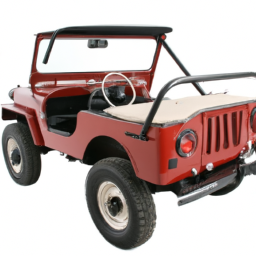
Download Jeep CJ-5A 1964-1968 Workshop Service Manual –

online
Replacing the ball joints on a 1964 Jeep CJ-5A is a task that requires careful attention to detail and a good understanding of automotive mechanics. click here for more details on the download manual…..


    1966 Jeep CJ-5 Test Drive – GR Auto Gallery See 100+ photos, pricing & specs at: https://www.grautogallery.com/vehicles ▻ Subscribe: …

    Battery drain, classic car edition, quick tutorial It seems that one of the most common and misunderstood problems i see in my daily business restoring and maintaining vintage …

Below is a detailed guide on how to perform this procedure, including descriptions of all necessary components and tools.

### Tools and Materials Needed

1. **Tools:**
– Floor jack and jack stands
– Socket and ratchet set (including extensions)
– Wrenches (including adjustable wrenches)
– Ball joint separator (pickle fork)
– Hammer
– Torque wrench
– Grease gun
– Pliers
– Safety glasses
– Gloves

2. **Parts:**
– New upper and lower ball joints (ensure they are compatible with a 1964 Jeep CJ-5A)
– New cotter pins (if applicable)
– New grease (for pre-lubricating the ball joints)
– New dust seals (if not included with the ball joints)

### Preparation

1. **Safety Precautions:**
– Always wear safety glasses and gloves.
– Ensure the work area is clean and well-lit.
– Make sure the vehicle is parked on a flat surface and the parking brake is engaged.

2. **Lift the Vehicle:**
– Use the floor jack to lift the front of the Jeep. Place jack stands under the frame or designated lifting points to secure the vehicle.

### Removing the Old Ball Joints

1. **Remove the Wheel:**
– Use a socket and ratchet to remove the lug nuts and take off the front wheel.

2. **Remove the Brake Caliper and Rotor (if applicable):**
If your Jeep has disc brakes, unbolt the brake caliper using the appropriate socket. Hang it out of the way using a bungee cord or rope (do not let it hang from the brake line).
– Remove the brake rotor If necessary.

3. **Remove the Steering Knuckle:**
– Locate the bolts securing the steering knuckle to the axle housing. These are typically large bolts.
– Use a socket and ratchet to remove these bolts.
– Carefully pull off the steering knuckle; you may need to gently tap it with a hammer If it’s stuck.

4. **Remove the Old Ball Joints:**
– The upper and lower ball joints are typically pressed into the steering knuckle. Use a ball joint separator (pickle fork) to separate the ball joint from the knuckle.
If your Jeep has retaining clips or bolts holding the ball joints in place, remove them first.
– Using a hammer and the ball joint separator, drive the ball joint out of the steering knuckle.

### Installing New Ball Joints

1. **Prepare the New Ball Joints:**
– Compare the new ball joints to the old ones to ensure they are the correct parts.
If your new ball joints have grease fittings, ensure they are oriented correctly.

2. **Install New Ball Joints:**
– Align the new ball joint with the hole in the steering knuckle.
– Using a press (or a hammer If necessary), carefully press the ball joint into place. Be careful not to damage the joint during this process.

3. **Reattach the Steering Knuckle:**
– Position the steering knuckle back onto the axle housing.
– Reinstall the boltsdownload Jeep CJ 5A 1964 workshop manual and torque them to the manufacturer’s specifications (check a service manual for specific torque values).
4. **Reattach the Brake Rotor and Caliper:**
If you removed the brake rotor, install it back onto the hub.
– Reattach the brake caliper and secure it with the bolts.

5. **Reinstall the Wheel:**
– Place the wheel back onto the hub and hand-tighten the lug nuts. Lower the vehicle from the jack stands and then torque the lug nuts to the manufacturer’s specifications.

### Final Steps

1. **Grease the Ball Joints:**
– Use a grease gun to apply grease to the new ball joints through their fittings, ensuring they are well-lubricated.

2. **Check Alignment:**
– After replacing ball joints, it’s advisable to have the vehicle’s alignment checked, as changes in suspension components can affect wheel alignment.

3. **Test Drive:**
– Take the vehicle for a short test drive to ensure everything is functioning correctly and listen for any unusual noises.

### Conclusion

Replacing ball joints on a 1964 Jeep CJ-5A can be a rewarding task If done carefully. Always consult a repair manual for specific details and torque specifications, and don’t hesitate to seek professional help If you feel unsure about any step in the process. Proper maintenance of ball joints is crucial for ensuring safe and reliable vehicle operation.
The camshaft seal is a critical component in an engine’s design, primarily responsible for preventing oil leaks from the camshaft housing. Typically made from durable materials such as rubber or silicone, the camshaft seal is a circular gasket that fits snugly around the camshaft as it exits the engine block or cylinder head. Its primary function is to maintain the lubrication system’s integrity by sealing the gap between the moving camshaft and the stationary engine components.

In an internal combustion engine, the camshaft plays a vital role in controlling the timing of the engine’s valves, which allows for the optimal intake of air-fuel mixture and exhaust expulsion. As the camshaft rotates, it generates movement that necessitates a reliable seal to prevent engine oil from leaking out, which could lead to a drop in oil pressure and potential engine damage. A faulty or worn camshaft seal can result in oil leaks, which not only pose risks to the engine’s performance But can also create hazards If oil drips onto hot engine parts.

Regular inspection and maintenance of the camshaft seal are essential, especially in older vehicles or those with high mileage. If a leak is detected, replacing the camshaft seal is crucial to preserving engine health, enhancing overall performance, and ensuring the longevity of the vehicle.

Download HYUNDAI R1200LC-9 Crawler Excavator Service Repair Manual –

australian
Replacing brake pads on a Hyundai R1200LC-9 Crawler Excavator involves several steps that should be performed in a careful and organized manner. click here for more details on the download manual…..


    Hyundai HX300L demo in quarry

    R1200LC-9A Working in California

Below, I’ve outlined the procedure in reverse order:

### 10. Reassemble the Components
– **Reinstall any removed components**: Ensure all parts that were taken off during the process are securely reattached.
– **Torque bolts**: Use a torque wrench to tighten all bolts to the manufacturer’s specifications.

### 9. Test the Brakes
– **Check brake operation**: Before putting the excavator back into operation, test the brakes to ensure they engage and release properly.
– **Look for leaks**: Inspect for any fluid leaks around the brake components.

### 8. Reconnect the Brake Lines
– **Reconnect hydraulic lines**: If any hydraulic lines were disconnected, make sure they are properly reattached and secure.

### 7. Install the New Brake Pads
– **Position the new pads**: Place the new brake pads into the caliper or designated housing.
– **Ensure correct alignment**: Make sure the pads are seated correctly against the rotor or drum.

### 6. Compress the Caliper Piston
– **Use a caliper tool**: If applicable, use a brake caliper tool to compress the caliper piston to make space for the new pads.

### 5. Remove the Old Brake Pads
– **Take out the old pads**: Carefully remove the old brake pads from the caliper or housing.
– **Inspect for wear**: Check the old pads for wear and ensure the rotor or drum is not damaged.

### 4. Access the Brake Assembly
– **Remove wheel or cover**: Depending on the excavator’s design, you may need to remove wheels or protective covers to access the brake assembly.
– **Unbolt the caliper or brake housing**: Remove any bolts or clips holding the caliper or brake assembly in place.

### 3. Prepare the Work Area
– **Ensure safety**: Park the excavator on a level surface and engage the parking brake. Use wheel chocks for added safety.
– **Gather tools and materials**: Have all necessary tools (wrenches, sockets, brake cleaner, new brake pads, etc.) and safety equipment ready.

### 2. Disconnect the Battery
– **Turn off the machine**: Ensure the excavator is powered down.
– **Disconnect the battery**: To prevent any electrical issues, disconnect the battery terminals.

### 1. Review the Service Manual
– **Consult the manual**: Before starting, review the Hyundai R1200LC-9 service manual for specific instructionsdownload HYUNDAI R1200LC 9 Crawler Excavator workshop manual and torque specifications related to brake pad replacement.

By following these steps in reverse order, you can effectively replace the brake pads on the Hyundai R1200LC-9 Crawler Excavator while ensuring safety and proper functionality. Always refer to the manufacturer’s guidelines for detailed procedures and specifications.
A jack stand is a vital safety tool used in automotive maintenance and repair, designed to support a vehicle when it has been lifted off the ground. Typically made from sturdy materials such as steel or heavy-duty aluminum, jack stands provide a stable and secure means of holding a vehicle in place after being elevated by a hydraulic jack or floor jack.

The primary purpose of a jack stand is to prevent a vehicle from accidentally falling while mechanics or DIY enthusiasts work underneath it. This is crucial because working under a raised vehicle poses significant risks, including severe injury or death if the vehicle were to collapse. Jack stands come in various sizes and weight capacities, allowing users to select a suitable option based on the vehicle’s weight and the height required for the job.

Most jack stands feature a ratchet mechanism that allows for height adjustment, enabling users to achieve the desired lift while ensuring stability. They typically have a wide base for enhanced support and stability, reducing the risk of tipping over. When using jack stands, it is essential to follow safety guidelines, including placing them on solid ground and using them in pairs to evenly distribute the vehicle’s weight. Overall, jack stands are indispensable for safe vehicle maintenance, promoting both efficiency and safety in automotive work.

Download 1997 Ford Expedition Service & Repair Manual –

online
Repairing the suspension strut tower on a Ford Expedition involves several steps. click here for more details on the download manual…..


    2007 Ford Expedition: Suspension Upgrade My air suspension went out on my truck, so I replaced it with a coil over suspension, but it’s not working out how I’d like. Happy to …

    WE INSTALL RUST REPAIR PATCHES ON THE ROCKER PANELS OF OUR 2007 Ford Expedition EL Budget friendly way to fix that unsightly rust along the rocker panel of 2007-2017 Ford Expedition and Lincoln Navigator EL …

Here’s a reverse order of how the process would typically be completed:

### 10. **Reassemble the Vehicle**
– Reinstall any components removed during disassembly, including the engine cover, plastic trim, and any other parts.
– Reconnect the battery and ensure all electrical connections are secure.

### 9. **Install the New strut Tower**
– Secure the new strut tower in place, following manufacturer specifications for torque settings.
– Ensure all bolts and nuts are tightened properly.

### 8. **Reattach the strut Assembly**
– Lift the strut assembly back into position and secure it to the strut tower using the appropriate bolts.
– Reconnect any sensors or wiring that were disconnected.

### 7. **Reinstall Suspension Components**
– Reattach any suspension components that were removed to access the strut tower, such as control arms or sway bar links.
– Ensure everything is properly aligned and secure.

### 6. **Check Alignment and Fit**
– Before final tightening, check that everything is aligned correctly and that there is no interference with other components.

### 5. **Remove the Old strut Tower**
unscrew and remove the damaged strut tower from its position.
– Be cautious of any residual components that may still be connected.

### 4. **Prepare the Work Area**
– Ensure the vehicle is on a level surface and secured with jack stands.
– Remove the wheel on the side where the strut tower repair is being performed.

### 3. **Disconnect Components**
– Disconnect components such as brake lines, ABS sensors, and any wiring harnesses that may obstruct the strut assembly.
– Remove the strut assembly from the vehicle.

### 2. **Access the strut Tower**
– Open the hooddownload Ford Exp workshop manual and remove any components obstructing access to the strut tower, such as the air intake or battery if necessary.
### 1. **Gather Tools and Parts**
– Collect all necessary tools (wrenches, sockets, torque wrench, etc.) and replacement parts (new strut tower, gaskets, etc.) before starting the repair.

### Note:
This is a general guideline and may vary depending on the specific model year and condition of the vehicle. Always consult a repair manual or professional service for detailed instructions tailored to your specific vehicle.
The high beam switch is a crucial component in a vehicle’s lighting system, responsible for controlling the high beam headlights. These headlights provide enhanced illumination, allowing drivers to see further down the road, especially in low-light conditions such as nighttime driving or poorly lit areas. The high beam switch can be located in various places within the vehicle, but it is most commonly found on the steering column or as a stalk on the left side of the steering wheel.

When activated, the high beam switch engages the high beam headlights, illuminating a broader and more intense beam of light. This is particularly useful for rural driving or on highways where there are few other vehicles, as it significantly increases visibility at greater distances. However, it is essential for drivers to use high beams judiciously, as they can cause glare and impair the vision of oncoming drivers.

Most vehicles are equipped with a mechanism that automatically dims the high beams when an oncoming vehicle is detected, known as automatic high beam control. This feature enhances safety by minimizing the risk of blinding other drivers. Additionally, the high beam switch often integrates with other lighting controls, allowing the driver to easily toggle between low and high beams as required by driving conditions. Overall, the high beam switch plays a pivotal role in ensuring safe nighttime driving and enhancing overall road visibility.

Download 2017 Mercedes-Benz E-Class E220d T-Modell (S213) All-Terrain OEM Download Service & Repair Manual Software –

repair
Replacing the struts on a Mercedes Benz E-Class E220d T Modell S213 All Terrain can seem daunting, especially if you have little mechanical experience. click here for more details on the download manual…..


    Start of production of the new Mercedes-Benz E-Class 2024 in plant Sindelfingen Start of production of the new 2024 Mercedes-Benz E-Class in plant Sindelfingen #E200, #E300, #E400, #E300e, #E400d Salon …

    Mercedes E 220 d All Terrain – Off-Road Drive 2017 Mercedes-Benz E 220 d All Terrain – Off-Road Drive. Color: Designo Hyacinth Red Metallic. Whether on rough tracks, …

However, I’ll break down the process into simple steps to help you understand what’s involved. Please remember that working on your vehicle can be dangerous, and if you’re not comfortable doing it yourself, it’s always best to consult a professional mechanic.

### Tools and Materials Needed:
– New struts (OEM recommended)
– Jack and jack stands
lug wrench
– Socket set
– Wrench set
– Torque wrench
– Screwdriver
– Spring compressor (if necessary)
– Safety goggles and gloves

### Step-by-Step Guide:

#### 1. **Preparation:**
– **Safety First:** Wear safety goggles and gloves to protect yourself.
– **Gather Tools:** Make sure you have all your tools and new struts ready.

#### 2. **Lift the Vehicle:**
– **Park on a Level Surface:** Ensure the car is parked on a flat, stable surface.
– **Loosen lug Nuts:** Before lifting the vehicle, use the lug wrench to slightly loosen the lug nuts on the wheel where you’ll be replacing the strut.
– **Jack Up the Vehicle:** Use a jack to lift the front or rear of the vehicle, depending on which strut you’re replacing. Make sure to place the jack stands securely under the frame to support the car.
– **Remove the Wheel:** Once the car is securely lifted and supported, remove the lug nuts completely and take off the wheel.

#### 3. **Remove the Old Strut:**
– **Locate the Strut:** The strut is typically located behind the wheel assembly. You may need to remove some components (like the brake line or sway bar link) to access it.
– **Unbolt the Strut:** Using the socket and wrench, remove the bolts that hold the strut to the steering knuckle and any bolts at the top of the strut (usually under the hood).
– **Carefully Remove the Strut:** Once all bolts are removed, carefully slide the strut out of its housing. If it’s stuck, gently wiggle it free.

#### 4. **Install the New Strut:**
– **Position the New Strut:** Place the new strut in the same position as the old one. It should slide into the housing easily.
– **Secure the Strut:** Reattach the bolts to the steering knuckle and tighten them securely. Then, tighten the bolts at the top of the strut.
– **Reattach Components:** If you removed any components (like brake lines or sway bar links), reattach them now.

#### 5. **Reinstall the Wheel:**
– **Put the Wheel Back On:** Place the wheel back onto the hub and hand-tighten the lug nuts.
– **Lower the Vehicle:** Carefully remove the jack stands and lower the vehicle back to the ground.

#### 6. **Tighten lug Nuts:**
– **Final Tightening:** Once the vehicle is on the ground, use the torque wrench to tighten the lug nuts to the manufacturer’s specifications. This ensures they are securely fastened.

#### 7. **Repeat as Necessary:**
– If you’re replacing multiple struts, repeat the above steps for each strut.

#### 8. **Test Drive:**
– **Check Your Work:** Once everything is back together, take the car for a short test drive to ensure everything feels right. Pay attention to any unusual noises or download Mercedes Benz E Class E220d T Modell S213 All Terrain OEM workshop manualhandling issues.

### Important Tips:
– **Consult Your Manual:** Always refer to your vehicle’s service manual for specific details and torque specifications.
– **Take Your Time:** Don’t rush through the process. If you Feel uncertain at any point, it’s wise to seek help from a professional.
– **Safety First:** Always ensure the vehicle is securely supported before working under it.

By following these steps, you should have a clearer understanding of how to replace the struts on your Mercedes Benz E-Class E220d T Modell S213 All Terrain. good luck, and stay safe!
The seat cushion is a fundamental component of automotive seating systems, playing a vital role in both comfort and safety for vehicle occupants. Positioned at the base of the seat, it serves as the primary support for the driver and passengers, influencing the overall driving experience. Typically made from various materials such as foam, gel, or air, the seat cushion is designed to absorb shock and provide a comfortable seating surface that contours to the body shape, distributing weight evenly.

One of the key functions of the seat cushion is to enhance comfort during long drives by reducing pressure points, which can lead to fatigue and discomfort. Manufacturers often employ advanced foam technologies, such as memory foam or high-resilience foam, to improve the cushioning effect and ensure longevity. Additionally, some premium vehicles feature heated or cooled seat cushions, enhancing passenger comfort in different weather conditions.

From a safety perspective, the seat cushion also plays a role in crash protection. It is engineered to work in conjunction with the seat frame and restraint systems, helping to keep occupants securely in place during an impact. Furthermore, in modern vehicles, seat cushions may integrate additional features like lumbar support and adjustable settings, allowing for personalized comfort and improved ergonomics. Overall, the seat cushion is a critical element that combines functionality, safety, and comfort, making it indispensable in the design of automotive interiors.