Download 2002 BMW 525I Service and Repair Manual –

stores
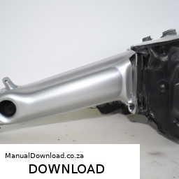
Replacing the clutch plate on a BMW 525i involves several steps and requires specific tools and components. click here for more details on the download manual…..


    BMW DENTS FIXED IN MINUTES! BMW 5 Series – 100% Glue Pull Dent Repair (Paintless Dent Removal) Paintless dent removal carried out by Ben at Dents Inc – Cheshire UK This video perfectly demonstrates how important it is to be …

    E30 Progress + E34 525i OVERHEATED! Time to remove the Cylinder Head… While I did say that we get to make the AN lines for the 86 E30 today I completely underestimated the cooler assembly so that will …

Below is a detailed guide, including descriptions of the tools needed for this task.

### Tools and Equipment Needed:

– **Socket Set**: A complete socket set (metric) will be required, including:
– **Ratchet**: For turning the sockets.
– **Extensions**: To reach fasteners in tight spaces.
– **Universal Joint**: For accessing bolts at angles.

– **Torque Wrench**: For tightening bolts to the manufacturer’s specifications.

– **Pliers**: For removing clips and holding components.

– **Screwdrivers**: Both flat-head and Phillips for various fasteners.

– **Clutch Alignment Tool**: This tool is crucial for aligning the new clutch disc with the flywheel during installation.

– **Transmission Jack or floor Jack**: To safely support and lower the transmission.

– **Creeper or Mechanic’s Mat**: For comfort while working underneath the vehicle.

– **Brake Cleaner**: To clean the surfaces of the flywheel and clutch components.

– **Rags or Shop Towels**: For cleaning and wiping away any spilled fluids.

– **Drip Pan**: To catch any fluids that may leak during the process.

– **Replacement Clutch Kit**: Ensure you have a complete kit that includes:
– **Clutch Disc**: The actual friction plate.
– **Pressure Plate**: The component that presses the clutch disc against the flywheel.
– **Release Bearing (Throw-out Bearing)**: The bearing that disengages the clutch when the pedal is pressed.

### Steps for Clutch Plate Replacement:

– **Preparation**:
– Park the vehicle on a flat surface and engage the parking brake.
Disconnect the negative battery terminal to prevent any electrical shorts.

– **Remove the Drive Shaft**:
– Depending on your model, locate and remove the bolts securing the drive shaft to the transmission.
– Carefully slide the drive shaft out and set it aside.

– **Access the Transmission**:
– Remove any components obstructing access to the transmission. This may include the exhaust system, heat shield, or crossmembers.
– Support the transmission using a transmission jack or floor jack.

– **Unbolt the Transmission**:
– Locate the bolts securing the transmission to the engine and remove them using the socket set.
– Carefully lower the transmission from the engine block. You may need to wiggle it free due to the input shaft being engaged in the clutch.

– **Remove the Old Clutch Assembly**:
– Once the transmission is removed, you will have access to the clutch assembly. Remove the pressure plate by unbolting it from the flywheel.
– Carefully pull off the clutch disc and inspect the flywheel for damage or excessive wear.

– **Clean the Flywheel**:
– Use brake cleaner and a rag to clean the surface of the flywheel, removing any debris or oil.

– **Install the New Clutch Kit**:
– Position the new clutch disc onto the flywheel. Use the clutch alignment tool to ensure it is centered.
– Install the new pressure plate over the clutch disc and tighten the bolts in a star pattern to ensure even pressure. Use the torque wrench to apply the correct torque as specified in the manufacturer’s manual.

– **Replace the Release Bearing**:
– Install the new release bearing onto the transmission input shaft If applicable.

– **Reinstall the Transmission**:
– Carefully lift the transmission back into position, ensuring the input shaft aligns with the clutch disc.
– Bolt the transmission back to the engine block securely.

– **Reinstall the Drive Shaft**:
– Reattach the drive shaft to the transmission, ensuring it is secured with the appropriate bolts.

– **Reassemble Any Removed Components**:
– Reinstall any components that were removed to access the transmission, such as the exhaust system or heat shields.

– **Reconnect the Battery**:
– Reconnect the negative battery terminal.

– **Test the Clutch**:
– Start the vehicledownload BMW 525I workshop manual and test the clutch operation. Ensure that the pedal feels normal and the clutch engages and disengages properly.

### Safety Tips:

– Always wear safety glasses and gloves when working on your vehicle.
– Make sure the vehicle is securely raised and supported with jack stands If you need to work underneath it.
If at any point you feel unsure about a step, consult a professional mechanic or refer to the vehicle’s service manual for additional guidance.

This guide should provide a comprehensive overview of the clutch plate replacement process for a BMW 525i. Always refer to the specific service manual for your vehicle for torque specifications and any model-specific procedures.
The fan clutch is a crucial component in a vehicle’s cooling system, designed to regulate the operation of the engine’s cooling fan. It plays a vital role in maintaining optimal engine temperatures, ensuring efficiency and preventing overheating. The fan clutch connects the engine’s cooling fan to the water pump shaft and is typically located between the fan blade and the engine.

There are two common types of fan clutches: thermal and electronic. A thermal fan clutch uses a bi-metallic strip that expands or contracts based on temperature. When the engine reaches a certain temperature, the bi-metallic strip activates a mechanism that engages the fan, allowing it to spin faster and increase airflow through the radiator. This helps dissipate heat more effectively. Conversely, when the engine cools down, the fan clutch disengages, allowing the fan to spin more slowly, which reduces drag on the engine and improves fuel efficiency.

Electronic fan clutches, on the other hand, utilize electronic sensors and signals from the engine control unit (ECU) to manage fan operation. This allows for more precise control over the cooling system, adapting to varying engine loads and temperatures.

A malfunctioning fan clutch can lead to overheating, reduced engine performance, and increased fuel consumption. Therefore, regular inspection and maintenance of this component are essential for optimal vehicle operation.

Download 2004 BMW 760Li (E65/E66) 7 Series OEM Download Service & Repair Manual Software –

service manual
Replacing the engine gasket on a BMW 760Li (E65/E66) is a complex task that requires a good understanding of automotive mechanics, as well as some specialized tools. click here for more details on the download manual…..


    bmw e65 760i custom exhaust Sound check after exhaust being modified on my 760i.

    DIY BMW E65 E66 7 series hidden dash menu Dash Camera: http://amzn.to/1Tci2uP UK Shoppers: http://amzn.to/1Slc5wS ******************************************************* All …

Below is a detailed guide to help you through the process, though it’s important to note that this is a high-level overview. Always refer to a service manual specific to your vehicle for precise instructions and torque specifications.

### Tools and Equipment Needed
1. **Basic Hand Tools**:
– Socket set (metric)
– Wrenches (metric)
– Screwdrivers (flat and Phillips)
– Torque wrench
– Pliers

2. **Specialized Tools**:
– Engine hoist (if necessary)
– Gasket scraper or razor blade
– Torque angle gauge
– Oil filter wrench
– Vacuum pump (for vacuum lines)

3. **Consumables**:
– New gaskets (OEM recommended)
– Engine oil
– Coolant
– Brake cleaner
– RTV silicone (if applicable)
– Engine degreaser

### Components Involved
1. **Engine Gaskets**:
– **Head Gasket**: Seals the cylinder head to the engine block.
– **Intake Manifold Gasket**: Seals the intake manifold to the cylinder head.
– **Exhaust Manifold Gasket**: Seals the exhaust manifold to the cylinder head.
– **Valve Cover Gasket**: Seals the valve cover to the cylinder head.
– **Oil Pan Gasket**: Seals the oil pan to the engine block.

2. **Engine Components**:
– **Cylinder Head**: Contains the combustion chambers, valves, and camshafts.
– **Intake Manifold**: Directs air and fuel into the engine.
– **Exhaust Manifold**: Directs exhaust gases out of the engine.
– **Valve Cover**: Covers the top of the engine cylinder head.
– **Oil Pan**: Holds the engine oil.

### Steps for Engine Gasket Replacement

#### 1. Preparation
– **Disconnect the Battery**: Ensure safety by disconnecting the negative terminal.
– **Drain Fluids**: Drain engine oil and coolant to prevent spills.

#### 2. Remove Components
– **Intake Manifold**:
– Disconnect throttle body, vacuum lines, and electrical connectors.
– Unbolt the intake manifold and carefully remove it.

– **Exhaust Manifold**:
– Disconnect exhaust pipes and associated sensors.
– Unbolt and remove the exhaust manifold.

– **Valve Covers**:
– Remove ignition coils and spark plugs (if applicable).
– Unbolt the valve covers and lift them off.

– **Cylinder Head**:
– Remove any remaining components attached to the cylinder head (e.g., camshaft timing chain, sensors).
– Unbolt the cylinder head in the correct sequence (refer to service manual).
– Carefully lift the cylinder head off the engine block.

#### 3. Clean Surfaces
– **Gasket Removal**: Use a gasket scraper or razor blade to remove old gaskets. Be careful not to scratch the mating surfaces.
– **Clean Surfaces**: Use brake cleaner and a clean rag to remove oil and debris from the mating surfaces.

#### 4. Install New Gaskets
– **Head Gasket**: Place the new head gasket onto the engine block, ensuring it’s aligned properly.
– **Intake and Exhaust Gaskets**: Install the new gaskets for the intake manifold and exhaust manifold.
– **Valve Cover Gasket**: Place the new gasket on the valve cover.

#### 5. Reassemble Components
– **Cylinder Head**: Carefully lower the cylinder head onto the block, ensuring the gasket stays in place.
– **Torque Head Bolts**: Torque the cylinder head bolts in the specified sequence and to the specified torque settings (refer to service manual).

– **Reinstall Valve Covers**: Bolt the valve covers back into place.
– **Reattach Exhaust Manifold**: Position the exhaust manifold with new gasketsdownload BMW 760Li E65 E66 7 OEM workshop manual and bolt it down.
– **Reattach Intake Manifold**: Position and bolt the intake manifold.

#### 6. Reconnect Components
– Reconnect all electrical connections, vacuum lines, and any other components that were removed.

#### 7. Fill Fluids
– **Engine Oil**: Replace the oil filter and fill the engine with the appropriate type and amount of engine oil.
– **Coolant**: Refill the cooling system with the recommended coolant.

#### 8. Final Steps
– **Reconnect Battery**: Reconnect the negative battery terminal.
– **Start the Engine**: Check for leaks and ensure the engine runs smoothly.
– **Check Systems**: Monitor for any warning lights and check fluid levels again after running the engine for a short period.

### Important Notes
– **Safety First**: Always wear safety glasses and gloves when working on a vehicle.
– **Consult Manual**: Refer to the BMW service manual for specific torque values and sequences.
– **Consider Professional Help**: If you lack experience, consider seeking help from a professional mechanic, as mistakes can lead to severe engine damage.

This guide provides an overview of the engine gasket replacement process for a BMW 760Li E65/E66. Proper care and attention to detail are essential for a successful repair.
A brake disc, also known as a brake rotor, is a critical component of a vehicle’s braking system, designed primarily to slow down or stop the vehicle by converting kinetic energy into thermal energy through friction. Typically made from cast iron or carbon composite materials, brake discs are circular plates that are mounted to the wheel hub. When the driver presses the brake pedal, hydraulic pressure is applied to brake calipers, which contain brake pads that clamp down onto the surface of the brake disc. This contact generates friction, which slows the rotation of the wheel and ultimately brings the vehicle to a stop.

Brake discs come in various designs, including vented, slotted, and drilled types, each engineered to improve performance under different conditions. Vented discs feature internal cooling channels that enhance heat dissipation, reducing the risk of brake fade during prolonged use. Slotted or drilled discs have grooves or holes that allow for better gas and moisture dissipation, further improving grip and performance, especially in wet conditions.

The maintenance of brake discs is paramount for vehicle safety. Over time, they can wear down or become warped due to excessive heat, necessitating regular inspections and replacements. High-performance vehicles may use upgraded brake discs to enhance stopping power and minimize fade during extreme driving conditions. Overall, the brake disc is an essential element in ensuring effective braking performance and vehicle safety.

Download 2008 BMW 1-Series COUPE E82 Service and Repair Manual –

workshop manual
Replacing the transmission fluid sensor on a BMW 1 Series Coupe (E82) can seem daunting, especially if you have little mechanical experience. click here for more details on the download manual…..


    BMW 1 Series Hidden Features!

    CHEAP APPLE CARPLAY HEAD UNIT FOR MY BMW 1 SERIES 135i E82 In this video, I’m showing you how to install an Apple Carplay/Android Auto head unit into a BMW 1 series E82. This unit is a great …

However, with the right tools and a step-by-step approach, you can tackle this task. Here’s a simplified guide to help you through the process.

### Tools and Materials Needed:
1. **Tools:**
socket set (including 10mm and 13mm sockets)
– Flathead screwdriver
– Ratchet wrench
– Torque wrench (for reassembly)
– Pliers
– Oil catch pan

2. **Materials:**
– New transmission fluid sensor
– New transmission fluid (if necessary)
– Rags or paper towels
– Safety glasses and gloves

### steps to Replace the Transmission Fluid Sensor:

#### 1. **Safety First**
– Park your car on a level surface and turn off the engine.
– Engage the parking brake.
wear safety glasses and gloves to protect yourself from any fluid spills.

#### 2. **Lift the Car**
– Use a jack to lift the front of the car and secure it on jack stands. This gives you better access to the transmission area.

#### 3. **Locate the Transmission Fluid Sensor**
– The transmission fluid sensor is typically located on the side of the transmission. It looks like a small plug and is usually near the fluid pan.
– You may need to remove a cover or some components to access it better.

#### 4. **Drain the Transmission Fluid**
– Place an oil catch pan underneath the transmission to catch any fluid that may leak out.
– Using a socket wrench, remove the bolts from the transmission pan (if necessary) to drain the fluid. Be careful, as the fluid can be hot and messy.

#### 5. **Disconnect the Old Sensor**
– Once you have access to the sensor, gently disconnect the wiring harness. There may be a clip or tab that you need to press to release it.
– Use the appropriate socket to unscrew the sensor from the transmission. Be cautious not to drop any debris into the transmission.

#### 6. **Install the New Sensor**
– Take your new sensor and screw it into place where the old One was. Use your hand to tighten it first, then use a torque wrench to tighten it to the manufacturer’s specifications (check your manual for the exact torque value).
– Reconnect the wiring harness to the new sensor, ensuring it clicks into place securely.

#### 7. **Reassemble the Transmission Pan (if removed)**
– If you removed the transmission pan, clean any old gasket material off the mating surface.
– Place a new gasket or sealant on the pan if required.
– Reattach the pan and tighten the bolts in a crisscross pattern to ensure even pressure.

#### 8. **Refill Transmission Fluid**
– If you drained the fluid, refill the transmission with the correct typedownload BMW 1 Series COUPE E82 workshop manual and amount of fluid as specified in your owner’s manual.
– Use a funnel to avoid spills and check for any leaks around the sensor area.

#### 9. **Lower the Car**
– Carefully remove the jack stands and lower the car back to the ground.

#### 10. **Test the New Sensor**
– Start the car and let it run for a few minutes. Check the dashboard for any warning lights related to the transmission.
– Take the car for a short test drive to ensure everything is functioning properly.

### Final Tips:
– Always refer to your vehicle’s service manual for specific instructions and torque specifications.
– If at any point you feel unsure, it may be wise to consult a professional mechanic.

By following these steps, you should be able to replace the transmission fluid sensor on your BMW 1 Series Coupe E82. good luck!
Keyless entry is an advanced automotive feature that enhances convenience and security for vehicle users. This system allows drivers to unlock and start their vehicles without the need for a traditional physical key. Instead, keyless entry utilizes a remote key fob or a smart key, which communicates wirelessly with the car’s electronic control unit.

When a driver approaches the vehicle with the key fob in their pocket or bag, sensors embedded in the car detect the fob’s proximity. This triggers the system to unlock the doors automatically, often accompanied by a welcoming light sequence. The driver can then enter the vehicle without fumbling for keys. Once inside, starting the engine is as simple as pressing a button, provided that the key fob is within the car’s interior.

Keyless entry systems often come with additional security features. For example, they may include rolling code technology, which changes the access code each time the key fob is used, making it significantly harder for potential thieves to replicate the signal. Some systems also offer features like remote locking and unlocking, allowing users to control their vehicle from a distance.

Overall, keyless entry systems represent a significant advancement in automotive technology, providing enhanced ease of use while also improving vehicle security. As vehicles become increasingly integrated with smart technology, keyless entry is likely to become a standard feature in many new models.

Download 2019 Audi S5 Download Service & Repair Manual –

owners manual
Performing engine diagnostics on an Audi S5 can seem daunting, but breaking it down into simple steps can make it manageable, even for those with little mechanical experience. click here for more details on the download manual…..


    NEW Wheels for the Audi S5! Looks AMAZING! Welcome back to the channel! In this video, we put are removing the stock wheels off the S5 to put on a set of aftermarket ones!

    B9 Audi S4/S5/RS4/RS5 Driveshaft Bearing Carrier UPGRADE!👀👌🏼😁 The JXB Performance Driveshaft Center Support Carrier Bearing Upgrade for the B9 Audi S4/S5/RS4/RS5 Has a Street(softer) …

Here’s an easy-to-follow guide:

### 1. **Gather Your Tools**
– **OBD-II Scanner**: This is a diagnostic tool that reads trouble codes from your vehicle’s computer. You can purchase one or find a local auto parts store that will lend or rent you one.
– **Basic Hand Tools**: A set of screwdrivers, wrenches, and pliers may come in handy if you need to inspect any components.

### 2. **Check for Warning Lights**
– Sit in your Audi S5 and turn the ignition to the “on” position (without starting the engine).
– Look for any warning lights on the dashboard, particularly the check Engine light (CEL). If it’s on or blinking, it indicates a problem.

### 3. **Connect the OBD-II Scanner**
– Locate the OBD-II port in your vehicle. In the Audi S5, it’s usually found below the dashboard near the steering column.
– Plug the OBD-II scanner into the port.
– Turn the ignition on (again, don’t start the engine).
– Follow the scanner’s instructions to read the trouble codes. These codes will give you clues about what might be wrong.

### 4. **Interpret the Codes**
– Once the scanner retrieves the codes, write them down. You can look them up in the scanner’s manual or search online for their meanings.
– Common codes may point to issues like misfires, oxygen sensor problems, or issues with the catalytic converter.

### 5. **Visual Inspection**
– Open the hood of your Audi S5.
– Look for any obvious signs of trouble:
– **Leaks**: Look for any fluids leaking (oil, coolant, etc.).
– **Worn Belts**: Check the condition of the belts; they should not be cracked or frayed.
– **Loose Connections**: Ensure all electrical connections are secure, especially those related to the Engine sensors.

### 6. **Check Fluid Levels**
– **Engine Oil**: Use the dipstick to check the oil level. Make sure it’s at the right level and the oil looks clean.
– **Coolant**: Check the coolant reservoir to ensure it’s at the proper level.
– **Brake Fluid**: Make sure your brake fluid is at the recommended level.

### 7. **Test Drive and Observe**
– If safe, take the car for a short drive. Pay attention to any unusual sounds, vibrations, or performance issues.
– If the check Engine light comes back on, make a note of any changes in performance.

### 8. **Seek Professional Help**
– If you find trouble codes that indicate serious issues (like Engine misfires or transmission problems), or if you’re uncomfortable performing any repairs, it’s best to consult a professional mechanic.

### 9. **Keep Records**
– Document any codes, symptoms,download Audi S5 workshop manual and repairs. This information can be very helpful for a mechanic if you need to take the car in for professional diagnostics.

### Conclusion
By following these steps, you can perform basic Engine diagnostics on your Audi S5. Remember, while this guide helps you identify potential issues, some problems may require professional expertise to fix. Don’t hesitate to seek help if you’re unsure about anything!
The trunk light, also known as the cargo light or boot light, is a vital component in automotive design, primarily serving the function of illuminating the trunk or cargo area of a vehicle. Typically located on the underside of the trunk lid or mounted on the side walls of the trunk, this small but essential light activates when the trunk is opened, providing visibility in low-light situations. Its primary purpose is to facilitate the easy loading and unloading of items, ensuring that drivers can see clearly when accessing their belongings, especially during nighttime or in poorly lit conditions.

Trunk lights are generally powered by the vehicle’s electrical system and can be LED or incandescent bulbs. LED lights are increasingly preferred due to their energy efficiency, longer lifespan, and brighter illumination. The light is usually wired to a switch that is activated when the trunk lid is opened, which may be a mechanical switch or a sensor that detects the lid’s position.

In addition to their practical function, trunk lights also enhance safety by preventing accidents or injuries that could occur from fumbling in the dark. Some modern vehicles may even include additional features, such as automatic shut-off timers or integration with the vehicle’s interior lighting system. Overall, the trunk light is a small yet significant feature that contributes to the overall functionality and convenience of a vehicle.

Download Kia Venga 2010 Service Manual –

bookshop
Installing a suspension lift kit on a Kia Venga can enhance its off-road capabilities and improve ground clearance. click here for more details on the download manual…..


    Kia Venga MPV review – CarBuyer Kia Venga MPV 2014 review: http://bit.ly/19YuYOS Subscribe to the Carbuyer YouTube channel: http://bit.ly/17k4fct Subscribe to …

    Rear End Noise? Diagnose and Fix a Differential in Your Car, Truck, or SUV If you are hearing clunking, rattling or grinding noises in the rear end of your rear wheel or four wheel drive vehicle, it may be a …

However, this process requires careful planning and execution. Below is a detailed guide outlining the tools and steps needed for a successful installation.

### Tools Required

– **Socket Set**: A complete metric socket set, including ratchets and extensions, to remove and tighten bolts.
– **Wrench Set**: A comprehensive set of combination wrenches for accessing tight spaces.
– **Torque Wrench**: To ensure all bolts are tightened to the manufacturer’s specifications.
– **Jack and Jack Stands**: A hydraulic jack for lifting the vehicle and jack stands for safety while working underneath.
– **Lug Wrench**: To remove the wheels.
– **Pry Bar**: For leveraging components, especially when removing old parts.
– **Spring Compressors**: Essential for safely compressing coil springs during removal and installation.
– **Cutting Tool**: A saw or cutting torch may be necessary if any modifications to brackets or body panels are required.
– **Drill and Drill Bits**: For creating new mounting points if needed.
– **Measuring Tape**: To measure suspension heights and ensure proper alignment.
– **Grease Gun**: To lubricate moving parts and fittings.
– **Safety Gear**: Gloves, goggles, and a dust mask to protect yourself during the installation.

### Installation Steps

– **Preparation**:
– Park the Kia Venga on a level surface, engage the parking brake, and disconnect the battery to prevent any electrical issues during the installation.
– Gather all tools and the lift kit parts to ensure everything is on hand.

– **Raise the Vehicle**:
– Use the jack to lift the front or rear of the vehicle, depending on which part of the suspension you are working on first.
– Secure the vehicle with jack stands to ensure safety while you are working underneath it.

– **Remove Wheels**:
– Using the lug wrench, remove the lug nuts and take off the wheels to access the suspension components.

– **Disconnect Suspension Components**:
– Start with the lower control arm, sway bar links, and shocks. Use the socket and wrench set to remove the bolts carefully.
– Depending on the lift kit design, you may need to remove the coil springs. Use spring compressors to safely compress the springs before removal.

– **Install Lift Kit Components**:
– Follow the manufacturer’s instructions for the lift kit, as each kit may have different components and installation methods.
install any new brackets, spacers, or lift struts as specified. Ensure that each component is aligned correctly.
– If the kit includes new shocks, replace the old shocks with the new ones at this stage.

– **Reassemble Suspension**:
– Once the lift kit components are installed, reattach the lower control arm, sway bar links, and any other suspension parts you previously removed.
– Ensure all bolts are tightened to the specified torque settings using the torque wrench.

– **Adjust Alignment**:
– After the suspension components are reattached, checkdownload Kia Venga workshop manual and adjust the alignment if necessary. this is crucial to ensure proper handling and tire wear.

– **Reinstall Wheels**:
– Put the wheels back on and hand-tighten the lug nuts.
– Lower the vehicle back to the ground, and then use the torque wrench to tighten the lug nuts to the manufacturer’s specifications.

– **Final Checks**:
– Reconnect the battery and check for any loose parts or unusual noises.
– Take the vehicle for a short test drive to ensure the lift kit is functioning correctly and there are no issues.

– **Post-Installation Maintenance**:
– Regularly check the suspension components and alignment, especially after the first few hundred miles, to ensure everything remains secure and properly adjusted.

### Notes

– Always consult the lift kit’s installation manual for model-specific instructions.
– If you’re unsure about any part of the installation, consider seeking professional assistance.
– Ensure the lift kit is suitable for the Kia Venga, as incorrect kits can lead to handling issues or damage.

Following these detailed steps should help you successfully install a suspension lift kit on your Kia Venga. Remember to prioritize safety and accuracy throughout the process.
The heater core is a vital component of a vehicle’s heating and cooling system, playing a crucial role in providing interior comfort during cold weather. It is essentially a small radiator located within the dashboard of the car, positioned in such a way that it can transfer heat from the engine’s coolant to the air that enters the cabin.

The heater core operates by circulating hot coolant from the engine through its channels. As the hot coolant passes through the core, a fan blows air over it, allowing the heat to transfer to the air. this heated air is then directed into the vehicle’s cabin through the ventilation system, warming the interior space for the occupants.

Heater cores are usually made of aluminum or copper and are designed in a way that maximizes surface area to enhance heat exchange efficiency. Over time, heater cores can become clogged with debris or suffer from corrosion, leading to diminished heating performance or even coolant leaks inside the cabin. Symptoms of a Failing heater core can include a sweet smell of coolant, foggy windows, or a lack of hot air from the vents.

Maintaining the heater core is important not only for comfort but also for the overall efficiency of the vehicle’s heating system. Regular inspections and coolant changes can help prolong its lifespan and ensure optimal operation.

Download HITACHI EX200 EX200LC Excavator EQUIPMENT PartsManual –

do your own repairs
Cleaning the intake manifold on a Hitachi EX200 or EX200LC excavator is an important maintenance task that helps ensure the engine runs efficiently. click here for more details on the download manual…..


    Cummins Engine All Parts Name & Image Full Details. Cummins Engine Parts Name. Hello Friends, Welcome to my channel ” MACHINE INTRODUCE ” दोस्तों में आप …

    excavator parts name in hindi | jcb excavator parts name parts name | @operatorekta excavator parts name in hind jcb excavator parts name parts name Excavator parts name Excavator parts in hindi Excavator parts …

Below is a step-by-step guide designed for individuals with little mechanical experience.

### Tools and Materials Needed:
– Safety Gloves and goggles
– Wrench set
– Socket set
– Screwdriver set
– Clean rags or shop towels
– Engine cleaner or degreaser
– Soft brush (like a toothbrush)
compressed air (optional)

### Step-by-Step Guide:

#### 1. **Safety First**
– **Turn off the Engine**: Make sure the excavator is turned off and cooled down.
– **Disconnect the Battery**: Disconnect the negative terminal of the battery to prevent any electrical issues while you work.

#### 2. **Locate the Intake Manifold**
– The intake manifold is usually located on the side of the engine. It’s a large metal component that connects to the engine block and has hoses leading to it.

#### 3. **Remove Obstructions**
If there are any hoses or components connected to the intake manifold, carefully remove them. Take note of where each hose connects, as you’ll need to put them back later. You can take pictures to help remember.

#### 4. **Unscrew the Intake Manifold**
using the wrench or socket set, carefully unscrew the bolts that hold the intake manifold in place. Keep track of the bolts, as you’ll need them to reattach the manifold.

#### 5. **Take Out the Intake Manifold**
– Once all the bolts are removed, gently lift the intake manifold off the engine. Be careful not to damage any gaskets (seals) that may be attached.

#### 6. **Clean the Manifold**
– **Inspect for Dirt and Debris**: Look for any dirt, carbon build-up, or other debris inside the manifold.
– **Apply Cleaner**: Spray the engine cleaner or degreaser inside the manifold. Let it sit for a few minutes to break down the grime.
– **Scrub**: Use the soft brush to scrub the inside of the manifold. Pay attention to any stubborn spots.
– **Wipe Clean**: Use clean rags or shop towels to wipe out all the residue and cleaner. Make sure it’s clean and dry before reinstalling.

#### 7. **Clean the Gaskets (if reusable)**
If the gaskets (seals) on the intake manifold are in good shape and reusable, wipe them down with a clean rag. If they are damaged, you will need to replace them.

#### 8. **Reinstall the Intake Manifold**
– Carefully place the intake manifold back onto the engine.
– Reattach any gaskets you removed (or new ones If needed).
– Tighten the bolts securely but be careful not to overtightendownload HITACHI EX200 EX200LC Excavator EQUIPMENT PartsManual workshop manual 
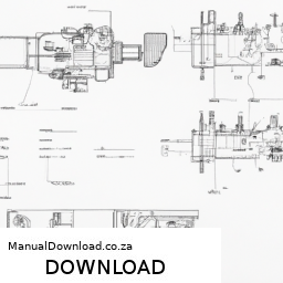
and damage the manifold.

#### 9. **Reconnect Hoses and Components**
– Reattach any hoses and components you removed earlier, ensuring they are secured properly.

#### 10. **Reconnect the Battery**
– Reconnect the negative terminal of the battery.

#### 11. **Test the Engine**
– Start the excavator and let it run for a few minutes. Check for any unusual noises or leaks around the intake manifold.

### Conclusion
Regularly cleaning the intake manifold helps maintain engine performance and prolongs the life of your excavator. If you encounter any issues during the process or feel uncertain, don’t hesitate to consult a professional or refer to the equipment’s service manual. Always prioritize safety and proper handling of tools.
A radiator hose is a crucial component of a vehicle’s cooling system, responsible for transporting coolant between the engine and the radiator. Typically made from durable rubber or silicone, these hoses are designed to withstand extreme temperatures and pressures generated during engine operation. There are generally two main types of radiator hoses: the upper hose and the lower hose.

The upper radiator hose connects the engine’s thermostat housing to the radiator, allowing hot coolant to flow from the engine to the radiator, where it cools down before being recirculated back into the engine through the lower hose. The lower hose, on the other hand, carries the cooled coolant back from the radiator to the engine, ensuring that the engine operates within its optimal temperature range.

Over time, radiator hoses can degrade due to heat, pressure, and exposure to various chemicals. Signs of wear include cracks, bulges, or leaks, which can lead to coolant loss and potential overheating of the engine. Therefore, regular inspection and maintenance of radiator hoses are essential for preventing costly repairs and ensuring the vehicle operates efficiently. In summary, radiator hoses play a vital role in maintaining engine temperature, contributing significantly to overall vehicle performance and longevity.

Download 1969 Ferrari 365 Gtc Gts 330 Gtc Service Manual –

purchase
Suspension knuckle repair on a Ferrari 365 GTC, GTS, or 330 GTC is a detailed process that requires precision and proper tools. click here for more details on the download manual…..


    New Ferrari 330 GTC wiring harness made by Auto Italia Sportiva This video highlights the completion of a new Ferrari 330 GTC wiring harness made by Auto Italia Sportiva also know as …

    1967 Ferrari 330GTC

Here’s a comprehensive guide to help you with the repair:

### Tools and equipment Needed
– **Torque Wrench**: Essential for ensuring bolts are tightened to the manufacturer’s specifications, preventing over-tightening or under-tightening.
– **Socket Set**: Includes various sizes to accommodate different bolt heads. Use a ratchet or breaker bar for leverage.
– **Pliers**: Needle-nose and standard pliers for gripping and manipulating small components.
– **Impact Wrench**: Speeds up the removal of stubborn bolts, especially those that may be rusted or corroded.
– **Hammer and Punch**: For driving out pins or bushings without damaging surrounding components.
– **Ball Joint Separator Tool**: Helps detach the ball joint from the suspension knuckle without causing damage.
– **Grease Gun**: For lubricating new components to ensure smooth operation.
– **Bearing Puller**: If the bearings in the knuckle need to be replaced, this tool is essential for removal without damage.
– **C-Clamp or Press**: Useful for compressing springs if the repair involves coil springs.
– **Cleaning Supplies**: Degreaser, Wire brushes, and lint-free cloths for cleaning parts before reassembly.
– **Safety Gear**: Gloves, goggles, and possibly a face shield to protect from debris and chemicals.

### Step-by-Step Repair Process
– **Preparation and Safety**:
– Park the vehicle on a level surface and engage the parking brake.
– Use wheel chocks to prevent the vehicle from rolling.
– Wear safety gear to protect against sharp objects and chemicals.

– **Raise the Vehicle**:
– Use a hydraulic jack to lift the vehicle and secure it on jack stands for safety.
– Remove the front wheels using a lug wrench.

– **Remove the Brake Components**:
– Detach the brake caliper and hang it securely (do not let it hang by the brake line).
– Remove the brake rotor by unscrewing any retaining screws or using a mallet if necessary.

– **Disconnect the Suspension Components**:
– Using the ball joint separator tool, detach the ball joint from the suspension knuckle.
– Remove any sway bar links or control arms connected to the knuckle.

– **Remove the Knuckle**:
– Unscrew the bolts securing the suspension knuckle to the strut assembly and steering components.
– Carefully slide the knuckle off of the strut and steering rack.

– **Inspect the Knuckle**:
– Check for cracks, bends, or wear on the knuckle. If damaged, it may need to be replaced.
– Inspect bearings and seals for wear or damage; replace if necessary.

– **Repair or Replace Components**:
– If bearings are damaged, use a bearing puller to remove them from the knuckle.
– Clean the knuckle thoroughly with degreaser and a Wire brush.
– Install new bearings, ensuring they are properly seated.

– **Reassemble the Knuckle**:
– Apply grease to any moving partsdownload Ferrari 365 Gtc Gts 330 Gtc workshop manual and install new seals if needed.
– Reattach the knuckle to the strut assembly and ensure all bolts are tightened to specifications using a torque wrench.

– **Reconnect Suspension Components**:
– Reattach the ball joint and any sway bar links or control arms.
ensure all components are secured and properly aligned.

– **Reinstall Brake Components**:
– Place the brake rotor back onto the hub and secure it.
– Reattach the brake caliper and ensure it operates smoothly.

– **Final Checks**:
– Double-check all connections and ensure everything is torqued to specifications.
– Reinstall the front wheels and lower the vehicle back to the ground.

– **Test Drive**:
– Take the vehicle for a short test drive to ensure everything is functioning correctly and listen for any unusual noises.

### Important Considerations
– **Consult OEM Specifications**: Always refer to the manufacturer’s service manual for specific torque values and procedures.
– **Quality Parts**: Use OEM or high-quality aftermarket parts to ensure reliability and performance.
– **Professional Help**: If unsure about any step or if specialized tools are needed, consider seeking professional assistance.

By following these detailed steps and using the appropriate tools, you can successfully repair the suspension knuckle on a Ferrari 365 GTC, GTS, or 330 GTC.
A lug wrench, also known as a tire iron or wheel brace, is an essential tool used for loosening and tightening the lug nuts that secure a vehicle’s wheels to its hub. Typically designed in a cross or L-shape, a lug wrench provides the necessary leverage to effectively apply torque to the lug nuts, which can be particularly useful when changing a tire or performing maintenance on a vehicle.

The design of a lug wrench often incorporates multiple socket sizes to accommodate different lug nut types, ensuring compatibility with a wide range of vehicles. The most common sizes found on lug wrenches are 17mm, 19mm, and 21mm, but variations exist depending on the make and model of the vehicle. Some lug wrenches also feature a telescoping handle, which extends to provide additional leverage, making it easier to loosen tightly secured lug nuts.

When using a lug wrench, it’s important to follow a specific sequence, especially when loosening lug nuts, to prevent warping the wheel or causing uneven stress. Generally, the process involves turning the wrench counterclockwise to loosen and clockwise to tighten the nuts.

Overall, the lug wrench is a critical component in automotive maintenance, enabling drivers to handle tire-related issues with greater ease and safety. Keeping one readily available in a vehicle’s trunk, along with a spare tire, is advisable for unforeseen situations such as flat tires.

Download 1985 Mercedes 190D Service Repair Manual 85 –

books
The Check Engine Light (CEL) on a 1985 Mercedes 190D can be a signal of various issues within the vehicle’s engine or emissions system. click here for more details on the download manual…..


    mercedes 190d problem

    190e m111 kompressor engine swap wiring w201 190e kompressor swaped m111 Instagram tag komprezor190.

To understand why the light is on and how to diagnose the problem, follow these steps, which include detailed descriptions of the components involved.

### tools and Equipment Needed:
1. **OBD-I Scanner**: Since the 1985 190D uses an early On-Board Diagnostics system (OBD-I), it’s essential to have a compatible scanner or a multimeter for some tests.
2. **Basic Hand Tools**: Wrenches, screwdrivers, pliers, etc., for inspecting and replacing components.
3. **Repair Manual**: A service manual specific to the 190D for reference on specifications and procedures.

### Step-by-Step Diagnosis

1. **Visual Inspection**:
– **Dashboard Indicator**: The Check Engine Light should be illuminated on the dashboard. This is usually located on the left side of the dashboard panel.
– **Wiring and Connectors**: Inspect the wiring harness and connectors under the hood for signs of wear, fraying, or corrosion. Ensure all connections are secure.

2. **Retrieve Diagnostic Codes**:
– **Location of Diagnostic Port**: The diagnostic port on the 190D is usually found under the dashboard near the driver’s seat. Look for a rectangular connector.
– **Connecting the Scanner**: connect your OBD-I scanner to the diagnostic port. Turn the ignition key to the “on” position without starting the engine.
– **Reading Codes**: Follow the scanner instructions to retrieve any stored trouble codes. Write down these codes for further investigation.

3. **Check Engine Components**:
– **Fuel System**:
– Inspect the fuel filter and fuel lines for clogs or leaks.
– Examine the fuel injectors for proper operation. A clogged injector can lead to poor engine performance, triggering the CEL.
– **Air Intake System**:
– Inspect the air filter. If it is clogged, replace it as restricted airflow can cause performance issues.
– Check the intake hoses for cracks or leaks that may allow unmetered air into the engine.
– **Exhaust System**:
– Examine the catalytic converter. A failing or clogged catalytic converter can trigger the CEL.
– Look for exhaust leaks, which can affect emissions readings.
– **Ignition System**:
– Check the condition of the spark plugs and wires. Worn or damaged spark plugs can lead to misfires and trigger the CEL.
– Inspect the ignition coil for proper function.
– **Sensors**:
– **Mass Air Flow (MAF) Sensor**: Located in the air intake path, it measures the amount of air entering the engine.
– **Throttle Position Sensor (TPS)**: Mounted on the throttle body, it monitors the position of the throttle plate.
– **Oxygen Sensors**: Located in the exhaust system, they monitor the level of oxygen in the exhaust gases.

4. **Perform Tests**:
– **Multimeter Checks**: Use a multimeter to check for proper voltagedownload Mercedes 190D 85 workshop manual and resistance in critical components like the MAF, TPS, and oxygen sensors.
– **Vacuum Leaks**: perform a vacuum leak test using a smoke machine or by spraying carburetor cleaner around the intake manifold and vacuum lines while the engine is running.

5. **Clear Codes and Test Drive**:
– If you have resolved the issue or replaced faulty components, use the OBD-I scanner to clear the trouble codes.
– Take the vehicle for a test drive to see if the Check Engine Light reappears. Monitor the performance and listen for unusual sounds.

6. **Professional Help**:
– If you cannot diagnose or resolve the issue on your own, consider taking the vehicle to a certified Mercedes-Benz mechanic who has the proper diagnostic tools and expertise.

### Conclusion

By following these steps, you can systematically diagnose and address the reason behind the Check Engine Light on your 1985 Mercedes 190D. Regular maintenance and inspections can help prevent issues and keep your vehicle running smoothly. Always refer to the vehicle’s service manual for specific details regarding components and systems.
The intake manifold gasket is a critical component in an internal combustion engine, serving as the seal between the intake manifold and the engine block or cylinder head. Its primary function is to prevent air and fuel mixture from leaking out of the intake system, ensuring that the engine receives the correct air-fuel ratio for optimal performance. Typically made from rubber, silicone, or composite materials, the gasket is designed to withstand high temperatures and pressures within the engine.

The intake manifold is responsible for directing the air-fuel mixture from the throttle body to the individual cylinders. A properly functioning intake manifold gasket is essential for maintaining engine efficiency and performance. If the gasket deteriorates or fails, it can lead to several problems, including vacuum leaks, which can cause rough idling, decreased fuel efficiency, and increased emissions. Symptoms of a faulty intake manifold gasket may also include engine misfires, poor acceleration, and a noticeable drop in power.

Replacement of the intake manifold gasket usually requires disassembling parts of the engine, making it a labor-intensive process. Regular maintenance and inspections can help identify potential issues before they escalate, ensuring the longevity and reliability of the engine. Overall, the intake manifold gasket plays a vital role in the overall performance and efficiency of an engine, making it an essential component for vehicle operation.

Download Mazda 626 MX6 Workshop Manual 1992 – 1997 –

diy
Changing the transmission fluid on a Mazda 626 or MX-6 is a straightforward process, but it requires attention to detail and the right tools. click here for more details on the download manual…..


    99 Mazda 626 water pump ,valve cover gaskets,timing belt,camshaft seals p1

    I completely forgot that this car existed ! 1994 Mazda MX-6 ! #mazda #mazdamx6 #1994 #coupe #rare…

Below is a comprehensive guide detailing every component involved in the fluid change process.

### tools and Materials Needed:

1. **Tools:**
– Socket set (including metric sockets)
– Wrenches (metric)
– Screwdrivers (flathead and Phillips)
– Transmission fluid pump or funnel with a long hose
– Drain pan
– Torque wrench (for reassembling)
– Pliers
– Jack and jack stands (if needed for better access)

2. **Materials:**
– New transmission fluid (check the owner’s manual for the correct type, usually Dexron III or Mercon)
– New transmission filter (if applicable)
– New gasket or RTV sealant (depending on the transmission type)
– Clean rags or paper towels
– Safety glasses
– Gloves

### Step-by-Step Process:

#### 1. Preparation:
– **Safety First:** Make sure the car is parked on a flat surface. Set the parking brake and wear safety glasses and gloves.
– **Gather tools and Materials:** Before starting, gather all tools and materials to avoid interruptions.

#### 2. Lift the Vehicle:
– **Jack Up the Car:** If needed for better access to the transmission pan, use a jack to lift the front of the vehicle. Secure the car with jack stands.

#### 3. Locate the Transmission Pan:
– **Identify the Transmission Pan:** The transmission pan is usually located at the bottom of the transmission. It is a rectangular metal pan that is held in place by several bolts.

#### 4. Drain the Old Transmission Fluid:
– **Position the Drain Pan:** Place a drain pan under the transmission pan to catch the old fluid.
– **Remove the Drain Plug:** If your transmission has a drain plug, use the appropriate socket to remove it and let the fluid drain into the pan. If not, proceed to the next step.
– **Loosen Pan Bolts:** If there’s no drain plug, carefully loosen the bolts around the transmission pan. Start from one side and gently pry the pan loose with a flathead screwdriver. Be prepared for additional fluid to spill out.
– **Remove the Pan:** Once the fluid is drained, remove the pan completely and set it aside.

#### 5. Replace the Transmission Filter (if applicable):
– **Locate the Filter:** Depending on your model, there may be a transmission filter inside the transmission.
– **Remove the Old Filter:** Unclip or unscrew the old filter, and carefully pull it out. Be ready for some residual fluid to spill out.
– **Install the New Filter:** Install the new filter in the same orientation as the old one, making sure it is seated properly.

#### 6. Clean the Transmission Pan:
– **Clean the Pan:** Thoroughly clean the inside of the transmission pan with a rag. Remove any old gasket material or debris.
– **Inspect the Magnet:** If your pan has a magnet (to catch metal shavings), clean it as well.

#### 7. Reinstall the Transmission Pan:
– **Apply Gasket or Sealant:** If your transmission requires a gasket, place a new gasket on the pan. If using RTV sealant, apply a continuous bead around the edge of the pan.
– **Reattach the Pan:** Align the pan with the transmission and reinstall the bolts. Tighten the bolts in a crisscross pattern to ensure even sealing. Refer to your service manual for the correct torque specifications.

#### 8. Refill with New Transmission Fluid:
– **Locate the Dipstick Tube:** Find the transmission dipstick tube under the hood. This is where you’ll add the new fluid.
– **Use a Funnel:** Insert a funnel into the dipstick tube.
– **Add New Transmission Fluid:** Pour the new transmission fluid into the funnel. Add fluid slowlydownload Mazda 626 MX6 workshop manual and check the level frequently using the dipstick to avoid overfilling. Refer to the owner’s manual for the correct fluid level specifications.

#### 9. Cycle the Transmission:
– **Start the Engine:** Start the engine and let it idle for a few minutes.
– **Shift Through Gears:** With your foot on the brake, shift through all the gears (P, R, N, D) to circulate the new fluid throughout the transmission.
– **Check Fluid Level Again:** After cycling through the gears, check the fluid level again and add more fluid if necessary.

#### 10. Final Checks:
– **Inspect for Leaks:** After you have finished, check the transmission pan and the drain plug for any leaks.
– **Dispose of Old Fluid Properly:** Make sure to dispose of the old transmission fluid at a recycling center or an auto parts store that takes used oil.

#### 11. Lower the Vehicle:
– **Remove Jack Stands:** If you used jack stands, carefully remove them and lower the vehicle back to the ground.

### Conclusion:
Changing the transmission fluid on a Mazda 626 or MX-6 can be done at home with the right tools and materials. Always remember to follow safety precautions and consult the vehicle’s service manual for specific instructions related to your model. Regular maintenance of the transmission fluid can prolong the life of your vehicle and ensure smooth operation.
The heater control valve is a crucial component in a vehicle’s heating and cooling system, primarily responsible for regulating the flow of engine coolant to the cabin heater core. Located typically within the engine compartment, it serves as a gatekeeper that controls the temperature of the air that is delivered into the cabin, ensuring passenger comfort during cold weather conditions.

When the driver adjusts the temperature settings on the climate control system, the heater control valve responds by opening or closing, thereby allowing a specific amount of hot coolant from the engine to flow into the heater core. As the coolant passes through the heater core, it transfers heat to the air that is blown into the cabin by the vehicle’s blower fan. Conversely, when the driver selects a cooler temperature, the valve partially or fully closes, limiting the flow of hot coolant, which results in cooler air being circulated inside the vehicle.

This component can be either manually operated or electronically controlled, depending on the vehicle’s design. Over time, heater control valves can wear out, leading to issues such as a lack of heat in the cabin, overheating, or coolant leaks. Regular maintenance and timely replacement of a faulty heater control valve are essential to ensure optimal performance of the vehicle’s heating system and to maintain passenger comfort.

Download Komatsu 930E-3 Dump Truck Workshop Service Manual for Repair –

service manual
Replacing the struts on a Komatsu 930E-3 dump truck is a complex task that requires mechanical expertise, proper tools, and safety precautions. click here for more details on the download manual…..


    That and they can’t haul as much #dumptruck #construction #heavyequipment #trucking #enddump https://linktr.ee/dauminiquethedumptruckdriver Trucking and Construction. Equipment ⬇️ Camera https://amzn.to/3oZL4UR …

    Komatsu 930E | SMS West – Teck Greenhills – Komatsu 930E-4 Electric Truck Komatsu 930E | This video is about SMS West – Teck Greenhills – Komatsu 930E-4 Electric Truck.

Here’s a step-by-step guide to help you understand the process and components involved in strut replacement. Please note that this is a general overview and you should refer to the specific service manual for your vehicle for detailed specifications and procedures.

### Components Involved in Strut Replacement

1. **Strut Assembly**: This is the main component that absorbs shocks and provides support to the vehicle’s suspension.
– **Spring**: Provides initial support and absorbs road shocks.
– **Shock Absorber**: Dampens the oscillation of the spring.
– **Strut Mount**: Connects the strut to the vehicle body and allows for rotation during steering.

2. **Mounting Bolts/Nuts**: These secure the strut assembly to the vehicle frame and suspension components.

3. **Control Arms**: These connect the strut assembly to the vehicle frame and help control the wheel’s motion.

4. **Steering Knuckle**: This is where the strut assembly connects to the wheel assembly.

5. **Brake Components**: The brake caliper and rotor may need to be removed for access to the strut.

### Tools Required

– Hydraulic jack and jack stands
– Socket set (metric and standard)
– Wrench set
– Strut spring compressor
– Torque wrench
– Screwdrivers
– Pliers
– Hammer or soft mallet
– Safety glasses and gloves

### Step-by-Step Strut Replacement Process

1. **Safety Precautions**:
– Park the dump truck on a flat surface and engage the parking brake.
– Wear safety glasses and gloves to protect yourself.

2. **Lift the Vehicle**:
– Use a hydraulic jack to lift the front or rear end of the dump truck, depending on which strut you are replacing.
– Place jack stands under the vehicle to provide extra support.

3. **Remove the Wheel**:
– Use a socket wrench to remove the lug nuts and take off the wheel to access the strut assembly.

4. **Disconnect Brake Components**:
– If necessary, remove the brake caliper and rotor to gain access to the strut assembly.
– Secure the caliper using a bungee cord or other means to avoid stressing the brake line.

5. **Remove the Strut Assembly**:
– Locate the upper strut mount bolts in the engine bay or under the hood. These are typically secured with nuts.
– Remove the nuts using the appropriate socket or wrench.
– Locate the lower mounting bolts on the control arm and remove them.
– Carefully lower the strut assembly from the vehicle.

6. **Compress the Spring**:
– Use a strut spring compressor to compress the coil spring on the strut assembly.
– Ensure that the spring is securely compressed and follow the manufacturer’s instructions for using the compressor.

7. **Remove the Old Strut**:
– Once the spring is compressed, remove the top strut mount nut and take off the mount.
– Remove the coil spring from the old strut.

8. **Install the New Strut**:
– Place the coil spring onto the new strut assembly and secure it with the top mount and nut.
– Make sure everything is aligned correctly.

9. **Reinstall the Strut Assembly**:
– Position the new strut assembly back into place, securing the upper mount first.
– Reinstall the lower mounting bolts to the control armdownload Komatsu 930E 3 Dump Truck workshop manual and tighten them to the manufacturer’s specifications.

10. **Reattach Brake Components**:
– Reinstall the brake rotor and caliper.
– Ensure that all components are securely fastened.

11. **Reinstall the Wheel**:
– Put the wheel back on and hand-tighten the lug nuts.
– Lower the truck back to the ground with the hydraulic jack and then use a torque wrench to tighten the lug nuts to the manufacturer’s specifications.

12. **Repeat for the Other Side**:
– If replacing both struts, repeat the process for the other side of the vehicle.

13. **Test the Vehicle**:
– Once both struts are replaced, perform a test drive to ensure proper operation.
– Check for any unusual noises or handling issues.

### Final Considerations

After replacing the struts, it is advisable to have the vehicle’s alignment checked and adjusted as necessary. This will help in ensuring proper handling and tire wear. Always refer to the service manual for specific torque settings and detailed procedures specific to the Komatsu 930E-3 dump truck. If you are not confident in your ability to perform this task, consult a professional mechanic.
The steering wheel is a crucial component of a vehicle’s steering system, serving as the primary interface between the driver and the vehicle’s direction control. Typically circular in shape and ergonomically designed for comfort, the steering wheel allows the driver to maneuver the vehicle effectively, providing both precision and feedback. It is usually mounted on a shaft that connects to the steering column, which translates the driver’s input into movement of the front wheels.

Made from various materials such as plastic, leather, or wood, the steering wheel often features controls for other vehicle functions, including audio systems, cruise control, and hands-free communication, allowing drivers to maintain focus on the road. Modern steering wheels may also include advanced technologies like heating, integrated airbags for safety, and even adaptive features that adjust the steering sensitivity based on speed.

The steering wheel’s design has evolved significantly over the decades, reflecting advancements in automotive technology and changing consumer preferences. For instance, some wheels are now equipped with paddle shifters for manual gear changes in performance vehicles. In addition to functionality, the aesthetics of the steering wheel can enhance the overall interior design of the vehicle, making it an important aspect of both usability and style. Overall, the steering wheel is not just a component; it embodies the driver’s connection to the vehicle, influencing the driving experience and enhancing safety on the road.