Download Alfa Romeo Montreal 1977 Factory Service Repair Manual –

purchase
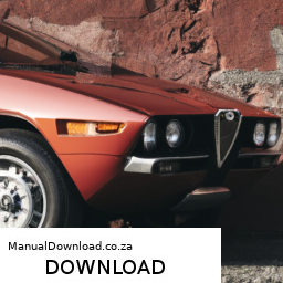
Repairing the gear shift linkage on an Alfa Romeo Montreal requires a good understanding of the vehicle’s transmission system and an appreciation for the unique features of this classic car. click here for more details on the download manual…..


    Alfa Montreal cylinder heads Part 2, working the bearing caps, more measurements, re-assembly The main purpose of this job was addressing a leaking head gasket on the right hand cylinder bank.While we had them off …

    1971 Alfa Romeo Montreal – Jay Leno’s Garage Is there any thing sexier than those headlights and the sound of its 3.0L V8? » Subscribe: http://bit.ly/JLGSubscribe » Visit the …

The gear shift linkage system connects the gear lever to the transmission, allowing the driver to select the appropriate gear. Here’s a detailed breakdown of the components involved in the gear shift linkage and how to repair it.

### components of the Gear Shift Linkage

1. **Gear Lever (Shifter)**: The gear lever is the component that the driver interacts with to select gears. It is usually mounted in the center console.

2. **Linkage Rods**: These rods connect the gear lever to the transmission. They are typically made of metal and may have adjustable lengths to fine-tune the shifting mechanism.

3. **Bushings**: These are small cylindrical components that provide a pivot point for the linkage rods. They reduce friction and wear and help maintain alignment.

4. **Connecting Joints**: These are often ball joints or clevis connections that allow for movement between the rods and the gear lever or transmission.

5. **Transmission Selector Shaft**: This is part of the transmission that the linkage connects to. It translates the movement from the gear lever into the appropriate gear selection.

6. **Mounting Brackets**: These hold the linkage rods in place and may be bolted to the chassis or transmission.

7. **Retaining Clips**: These small clips secure the linkage components to prevent them from disconnecting during operation.

### Tools and Materials Needed

– Socket set and wrenches
– Screwdrivers (flathead and Phillips)
– Pliers
– Torque wrench
– Replacement bushings and linkage rods (if necessary)
– Grease or lubricant
– Cleaning cloths
safety glasses and gloves

### Steps for Gear Shift Linkage Repair

#### 1. safety First
– Ensure the vehicle is parked on a level surface.
– Disconnect the battery to prevent any electrical issues while working on the vehicle.

#### 2. Remove the Center Console
– Carefully remove any trim panels surrounding the gear lever.
– Unscrew and lift the center console to access the gear lever assembly and linkage underneath.

#### 3. Inspect the Gear Lever
– Check for any play in the gear lever itself. If it feels loose, the issue may lie with the bushings or the connection to the linkage.

#### 4. Examine the Linkage Components
– Inspect the linkage rods for any signs of wear, bending, or damage.
– Check the bushings for deterioration or wear. They should be firm and not cracked or broken.
– Ensure that the connecting joints are not excessively worn and can move freely.

#### 5. Disconnect the Linkage
– Carefully remove the retaining clips that hold the linkage rods in place.
– Disconnect the rods from both the gear lever and the transmission selector shaft.
– Keep track of the order and orientation of the components for reassembly.

#### 6. Replace Worn Components
– If any bushings or rods are worn, replace them with new parts. Make sure to use components that are compatible with the Alfa Romeo Montreal.
– Apply grease to the new bushings before installation to reduce friction.

#### 7. Reassemble the Linkage
– Reconnect the linkage rods to the gear leverdownload Alfa Romeo Montreal workshop manual and transmission selector shaft.
– Ensure that all connections are secure and that the retaining clips are properly installed.

#### 8. Adjust the Linkage
– If your linkage has adjustable rods, make necessary adjustments to ensure proper alignment and movement. This may require trial and error to achieve smooth shifting.

#### 9. Reinstall the Center Console
– Once the linkage is reconnected and adjusted, carefully place the center console back in position.
– Reattach any trim panels and secure the center console with screws.

#### 10. Test the Gear Shift
– Reconnect the battery and start the engine.
– Test the gear lever to ensure smooth and precise shifting through all gears.
– If any issues arise, double-check the adjustments and connections.

#### 11. Final Inspection
– After confirming that everything is functioning properly, perform a final inspection of the work area to ensure no tools or parts are left behind.

### Conclusion

Repairing the gear shift linkage on an Alfa Romeo Montreal can enhance the driving experience by ensuring smooth and accurate gear changes. By carefully inspecting, replacing, and adjusting the components, you can restore the functionality of the gear shift linkage. Always refer to the vehicle’s service manual for specific torque specifications and diagrams to assist with the repair process. If you are unsure or uncomfortable with any part of the process, consider seeking help from a professional mechanic familiar with classic Alfa Romeo vehicles.
A heat shield is a critical component in automotive design, primarily serving to protect various parts of a vehicle from the intense heat generated by the engine and exhaust systems. Positioned strategically around parts that are susceptible to heat damage, such as fuel lines, electrical systems, and sensitive components, heat shields are essential for ensuring the vehicle’s overall safety and performance.

Typically made from materials such as aluminum, stainless steel, or specialized heat-resistant composites, heat shields are designed to reflect and dissipate heat rather than absorb it. This reflective capability is crucial in preventing heat buildup, which can lead to component failure, diminished efficiency, or even fire hazards. The design of a heat shield often incorporates air gaps or insulation layers to enhance its thermal protection properties.

In addition to their protective function, heat shields play a role in improving vehicle efficiency. By keeping critical components at optimal operating temperatures, they help maintain fuel efficiency and reduce emissions. Heat shields are commonly found in various locations within a vehicle, including around the exhaust manifold, catalytic converters, and undercarriage areas.

Overall, the heat shield is an unsung hero of automotive engineering, contributing significantly to the longevity, safety, and performance of modern vehicles while allowing for the safe operation of high-temperature components.

Download 1998 Subaru Impreza Service & Repair Manual Software –

service
Replacing the input shaft bearing on a Subaru Impreza can be a complex task that requires mechanical knowledge and the right tools. click here for more details on the download manual…..


    Diagnostic Scan Tools For DIY & Professional Subaru Repair. High & Low, Pros & Cons. Please Like, Comment, and Share. Be sure to subscribe for future videos. Don’t forget to hit the bell icon for notifications. YouTube …

    Subaru Parts and Service – Checking Engine Oil Schedule your service here https://www.subaru.com/owners/schedule-service.html. Stay up to date on Subaru by following us on …

The input shaft bearing is typically part of the transmission assembly, and its replacement will involve disassembling parts of the drivetrain. Below is a detailed step-by-step guide for this process.

### Tools and Materials Needed:

1. **Tools:**
– Socket set (metric)
– Wrenches (metric)
– Torque wrench
– Screwdrivers (flathead and Phillips)
– Pliers
– Hammer
– Bearing puller or slide hammer (for removing the old bearing)
– Gear puller (if necessary)
– Punch or chisel (for removing the old bearing race)
– Heat gun or torch (optional, for heating the new bearing for easier installation)
– Gasket scraper or razor blade
– Cleaning solvent
shop towel or rag
– Safety glasses and gloves

2. **Materials:**
– New input shaft bearing
– Transmission fluid (if the fluid needs to be replaced)
– Gasket or RTV sealant (if applicable)
– Grease (for lubrication of components)

### Procedure:

#### 1. **Preparation:**
– **Safety First:** Ensure the vehicle is on a flat surface. engage the parking brake and wear safety glasses and gloves.
– **Disconnect the Battery:** Disconnect the negative terminal to prevent any electrical issues.

#### 2. **Lift the Vehicle:**
– Use a jack to lift the front of the vehicle and secure it with jack stands. Ensure the vehicle is stable before working underneath.

#### 3. **Remove the Transmission:**
– **Drain Transmission Fluid:** Place a drain pan under the transmission and remove the drain plug to let the fluid flow out.
– **Remove Driveshaft (if applicable):** If your model has a driveshaft, remove it by unbolting the universal joint flanges on both ends.
– **Disconnect Linkages:** Remove any shift linkages and electrical connectors attached to the transmission.
– **Remove Transmission Mounts:** Unbolt the transmission from its mounts and support it with a transmission jack.
– **Unbolt Transmission from Engine:** Carefully unbolt the transmission from the engine. This usually involves several bolts around the bell housing.
– **Slide the Transmission Out:** Once everything is disconnected, carefully slide the transmission away from the engine.

#### 4. **Access the Input Shaft Bearing:**
– **Remove the Transmission Case:** If the input shaft bearing is located inside the transmission, you will need to remove the transmission case. Unbolt it carefully, keeping track of all bolts and their locations.
– **Remove the Input Shaft:** Once the case is open, you can access the input shaft. Carefully pull it out, ensuring you don’t damage any other components.

#### 5. **Remove the Old Input Shaft Bearing:**
– **Inspect the Bearing:** Check the condition of the bearing. If it’s worn or damaged, it needs replacement.
– **Remove the Bearing:** Use a bearing puller to extract the old bearing from the transmission case. If the bearing is stubborn, you can use a heat gun to warm the area around the bearing, which will expand the metal and make removal easier.
– **Clean the Area:** Once the old bearing is removed, clean the seating area thoroughly with a solvent and a rag.

#### 6. **Install the New Input Shaft Bearing:**
– **Prepare the New Bearing:** If you are using a press-fit bearing, you can warm it gently with a heat gun to help it fit easier.
– **Press the New Bearing in Place:** Position the new bearing in the bearing housing and carefully press it in using a bearing installer tool or a suitable-sized socket. Ensure it is seated evenly.
– **Check for Proper Installation:** Ensure the bearing is flush against the housingdownload Subaru Impreza workshop manual and spins freely without any binding.

#### 7. **Reassemble the Transmission:**
– **Reinstall the Input Shaft:** Insert the input shaft back into the transmission, ensuring it aligns properly with the new bearing.
– **Reassemble the Transmission Case:** Place the transmission case back together, ensuring any gaskets or sealant are properly applied.
– **Torque the Bolts:** Use a torque wrench to tighten all bolts to the manufacturer’s specifications.

#### 8. **Reinstall the Transmission:**
– **Align and Bolt the Transmission to the Engine:** Carefully slide the transmission back into position and bolt it to the engine.
– **Reconnect Transmission Mounts:** Secure the transmission mounts.
– **Reconnect Linkages and Driveshaft:** Attach any shift linkages and electrical connectors, and reinstall the driveshaft if removed.

#### 9. **Refill Transmission Fluid:**
– **Fill with New Transmission Fluid:** Refill the transmission with the recommended type of fluid through the fill hole.

#### 10. **Final Steps:**
– **Reconnect the Battery:** Reattach the negative terminal.
– **Lower the Vehicle:** Remove the jack stands and lower the vehicle.
– **Test Drive:** Take the car for a test drive to ensure everything is functioning correctly.

### Conclusion:
This is a general guideline for replacing the input shaft bearing on a Subaru Impreza. The specific steps may vary depending on the model year and engine variant. Always refer to a service manual specific to your vehicle for exact details and specifications. If you feel unsure about any part of the process, it may be best to consult a professional mechanic.
The front axle is a critical component of a vehicle’s suspension and drivetrain system, serving as a structural framework that connects the front wheels and supports the weight of the vehicle. It plays a pivotal role in the steering mechanism, stability, and overall handling of the car. Typically made from high-strength steel or aluminum, the front axle must withstand significant stresses and strains during operation, including forces generated during acceleration, braking, and cornering.

The front axle is composed of two main parts: the axle beam and the differential, if applicable. The axle beam is a solid or tubular structure that provides rigidity and support to the wheels. In vehicles with independent suspension systems, the front axle may consist of two separate half-axles that allow each wheel to move independently, enhancing ride comfort and handling.

In addition to supporting the weight of the vehicle and allowing for wheel rotation, the front axle is also integral to the vehicle’s steering system. It houses components like the wheel hubs and bearings, which facilitate smooth wheel movement. In front-wheel drive vehicles, the front axle also transmits power from the engine to the wheels, making it essential for vehicle propulsion. Proper maintenance of the front axle, including regular inspections and lubrication, is crucial to ensure safe and efficient vehicle operation, as wear and tear can lead to performance issues and compromised safety.

Download Hyundai HB90 and HB100 BACKHOE Loader Operating Manual –

online
Replacing the lower control arm on a Hyundai HB90 or HB100 backhoe loader involves several steps and requires specific tools and safety precautions. click here for more details on the download manual…..


      (28) JCB machine Hyundai H930s working and funny moment Subscribe karain ( Kashmir tractors ) ko aur agr video achu lagy to dostun k sath shere lazmi karain…. ko JCB kehty hein… chahay …

    Here’s a detailed guide to help you through the process:

    ### Tools and Equipment Needed

    – **Safety Gear**
    – Safety glasses: Protects your eyes from debris during the process.
    – Gloves: provides hand protection and better grip on tools.
    – Steel-toed boots: Ensures foot protection against heavy objects.

    – **Basic Hand Tools**
    – Socket set: A range of sockets (metric sizes, typically) to fit various bolts and nuts.
    – Wrench set: Open-end or box-end wrenches for loosening and tightening nuts and bolts.
    – Torque wrench: To ensure bolts are tightened to manufacturer specifications.
    – Hammer: For tapping stubborn parts or aligning components.

    – **Specialized Tools**
    – Ball joint separator: Helps remove and install ball joints without damage.
    – Pry bar: Useful for leverage when separating components.
    – Jack and jack stands: To safely lift and support the backhoe loader while working underneath.
    – Impact wrench: For quicker removal of bolts, particularly those that are rusted or torqued tightly.

    – **Miscellaneous Supplies**
    – Lubricants (e.g., WD-40 or penetrating oil): To help loosen rusted or seized bolts.
    – Replacement lower control arm: Ensure it’s the correct part for your specific model.
    – New hardware (if needed): Bolts, nuts, and washers that may need replacement.

    ### Replacement Process

    – **Preparation**
    – Park the backhoe loader on a flat, stable surface and engage the parking brake.
    – Place wheel chocks behind the wheels to prevent movement.
    – Disconnect the battery to avoid any electrical issues.

    – **Lifting the Vehicle**
    – Use a jack to lift the backhoe loader from the designated lifting points.
    – Secure the vehicle with jack stands to ensure stability while you work underneath.

    – **Remove the Wheel (If Applicable)**
    – If the lower control arm is behind the wheel, use a lug wrench to remove the lug nuts and take off the wheel.

    – **Disconnect the Lower Control Arm**
    – Locate the bolts securing the lower control arm to the chassis and the wheel hub.
    – Apply penetrating oil to the bolts if they appear rusted; allow it to soak for a few minutes.
    – Use the socket or impact wrench to remove the bolts carefully. Keep track of the order and orientation for reinstallation.

    – **Separate the Ball Joint**
    – If the lower control arm has a ball joint, use a ball joint separator to detach it from the knuckle.
    – A hammer can be used gently on the separator to help loosen the joint if necessary.

    – **Remove the Lower Control Arm**
    – Once all bolts and connections are removed, carefully take out the lower control arm from its mounting points. You may need to wiggle it slightly to release it completely.

    – **Install the New Lower Control Arm**
    – Position the new lower control arm in place, ensuring it aligns correctly with the mounting points.
    – Insertdownload Hyundai HB90 HB100 BACKHOE Loader workshop manual and hand-tighten the bolts to secure the control arm.

    – **Reattach the Ball Joint**
    – If applicable, insert the ball joint back into the knuckle and secure it as per manufacturer specifications. Use a torque wrench to tighten the bolts to the recommended settings.

    – **Reinstall the Wheel**
    – If you removed the wheel, place it back on and hand-tighten the lug nuts.
    – Lower the vehicle from the jack stands and use the torque wrench to tighten the lug nuts to the proper specifications.

    – **Final Checks**
    – Double-check all connections and bolts to ensure everything is secure.
    – Reconnect the battery.
    – Lower the backhoe loader completely and perform a test of the suspension and steering to ensure everything operates correctly.

    ### Post-Replacement Maintenance

    – **Inspection**
    – After replacing the lower control arm, regularly inspect the area for any signs of wear or damage.
    – Keep an eye on the alignment, as replacing control arms can affect vehicle alignment.

    – **Documentation**
    – Document the replacement in your maintenance log for future reference.

    By following these steps carefully and using the right tools, you can successfully replace the lower control arm on a Hyundai HB90 or HB100 backhoe loader. Always refer to the vehicle’s service manual for specific torque specifications and safety guidelines.
    An oil filter is a critical component in an internal combustion engine’s lubrication system, designed to remove contaminants from engine oil. The primary function of the oil filter is to ensure that the engine oil remains clean and free from debris, dirt, metal particles, and other impurities that can accumulate over time and potentially damage engine components.

    Oil filters come in various designs, including spin-on filters and cartridge filters, but they all operate on the same basic principle: as engine oil circulates through the engine, it passes through the filter, where contaminants are trapped in a filtering media, typically made of synthetic fibers or cellulose. This filtration process helps maintain the oil’s viscosity and lubricating properties, which are essential for reducing friction and wear between moving parts.

    Regular replacement of the oil filter is crucial for optimal engine performance. A clogged or dirty filter can restrict oil flow, leading to inadequate lubrication, increased engine wear, and overheating. Most vehicle maintenance schedules recommend changing the oil filter along with the engine oil at regular intervals, often every 3,000 to 7,500 miles, depending on the vehicle and oil type.

    In summary, the oil filter plays a vital role in engine longevity and efficiency by ensuring that the oil circulating through the engine remains clean, allowing it to effectively lubricate and protect vital components from wear and tear.

    Download Fiat Kobelco Compact LINE W80 Mini Wheel Loaders* Factory Service / Repair/ Workshop Manual ! –

    books
    Repairing the alternator on a Fiat Kobelco Compact LINE W80 Mini Wheel Loader involves several steps. click here for more details on the download manual…..


      Diesel Injection Pump (IN LINE 6 CYLINDER HIGHPRESSURE DIESELPUMP) #injectionpump #fuelpump #dies… Diesel Injection Pump (IN LINE 6 CYLINDER HIGHPRESSURE DIESELPUMP) #injectionpump #fuelpump #diesel #dieselpump …

    Below is a detailed guide, broken down into bullet points, outlining the tools needed and the step-by-step process for the repair.

    ### Tools Required:
    – **Socket Wrench Set**: For loosening and tightening various bolts and nuts on the alternator.
    – **Torque Wrench**: To ensure that bolts are tightened to the manufacturer’s specifications.
    – **Screwdrivers (Flathead and Phillips)**: For removing any covers or panels that may obstruct access to the alternator.
    – **Pliers**: To help with disconnecting and securing electrical connectors.
    – **Wire Brush or Sandpaper**: For cleaning the electrical connections and the mounting area.
    – **Multimeter**: To test the output voltage of the alternator and diagnose issues.
    – **Belt tension Gauge**: To ensure proper tension on the alternator belt (if applicable).
    – **Replacement Parts**: New alternator or alternator components (if needed), such as brushes or diodes.
    – **Safety Gear**: Gloves, safety glasses, and possibly a hard hat.

    ### Steps to Repair the Alternator:

    – **Safety First**:
    ensure the equipment is turned off and parked on a level surface.
    – Engage the parking brake and disconnect the battery to avoid any electrical shorts.

    – **Access the Alternator**:
    – Remove any covers or panels that may obstruct access to the alternator. Use screwdrivers to take out screws or bolts securing these components.
    – Locate the alternator, typically mounted on the engine block.

    – **Disconnect electrical Connections**:
    – Carefully disconnect the wiring harness from the alternator. Use pliers to gently pull on the connectors without damaging them.
    – Remove the positive and negative battery cables if they are still connected to prevent any electrical hazard.

    – **Remove the Alternator Belt**:
    – If applicable, use a wrench to loosen the tensioner pulley and remove the belt from the alternator. ensure to note the routing of the belt for reinstallation.

    – **Unscrew the Alternator**:
    – Use a socket wrench to remove the bolts securing the alternator to its mount. Keep these bolts in a safe place for reinstallation.

    – **Inspect the Alternator**:
    – Once removed, inspect the alternator for any visible signs of wear or damage. Look for burnt-out diodes, worn brushes, or damaged bearings.
    – Use a multimeter to check the output voltage. A healthy alternator should produce around 13.5 to 14.5 volts when running.

    – **Repair or Replace**:
    – If the alternator is repairable, replace worn components such as brushes or diodes. Follow the manufacturer’s guidelines for replacement parts.
    – If the alternator is beyond repair, install the new alternator in its place. ensure the mounting holes align correctly.

    – **Reinstall the Alternator**:
    – Secure the alternator back onto its mount using the original bolts. Tighten them to the manufacturer’s specifications using a torque wrench.

    – **Reconnect the Belt**:
    – If applicable, reroute the alternator belt according to the noted configurationdownload Fiat Kobelco Compact LINE W80 Mini Wheel Loaders workshop manual and adjust the tension using the tensioner pulley. Use a belt tension gauge to ensure proper tension.

    – **Reconnect electrical Connections**:
    – Reattach the wiring harness and ensure all connections are secure. Connect the positive and negative battery cables.

    – **Test the System**:
    – Reconnect the battery and start the engine. Check the voltage output at the alternator using a multimeter to ensure it is functioning correctly.
    – Observe the alternator for any unusual noises or issues during operation.

    – **Final Checks**:
    – Replace any covers or panels removed earlier and secure them with screws or bolts.
    – Dispose of any old parts or materials safely.

    ### Conclusion:
    Following these steps will help you successfully repair the alternator on a Fiat Kobelco Compact LINE W80 Mini Wheel Loader. Always refer to the manufacturer’s service manual for specific instructions and safety guidelines tailored to your equipment.
    A wheel lock is a vital security component designed to prevent the theft of wheels and tires from vehicles. It usually consists of a specialized lug nut or bolt that requires a unique key or adapter for removal, making it nearly impossible for thieves to detach the wheels without the proper tool. Wheel locks are typically made from hardened steel, providing durability and resistance against cutting and impact tools.

    The installation of wheel locks is straightforward; they replace one or more of the standard lug nuts on each wheel. The locking mechanism is characterized by a unique pattern or shape that corresponds to a specific key. This means that even if a thief possesses a standard set of tools, they would be unable to remove the locked wheel without the corresponding key.

    In addition to enhancing security, wheel locks also serve as a visual deterrent. The presence of wheel locks can make a vehicle less attractive to potential thieves, who might opt for easier targets. While no security measure is foolproof, wheel locks significantly increase the difficulty and time required to steal wheels, thereby reducing the likelihood of theft.

    Overall, wheel locks are an essential investment for vehicle owners who want to protect their wheels and tires from theft, especially in areas where such incidents are prevalent. They offer peace of mind and contribute to the overall security strategy for personal vehicles, car dealerships, and rental agencies alike.

    Download 2000 BMW 523i (E39) 5 Series OEM Download Service & Repair Manual Software –

    get
    Certainly! click here for more details on the download manual…..


      bmw e39 rebuild A failed attempt to properly complete rust removal and paint job A second attempt to save this e39.

      BMW E39: How to remove / replace radiator DIY. Hello! This is a DIY guide to show you how you can remove and replace a radiator on a BMW 5 series. Same procedure apply to …

    Here’s a step-by-step guide for replacing the clutch master cylinder on a BMW 523i E39, presented in reverse order:

    ### 7. Reattach the Battery
    – **Reconnect the negative battery terminal** to restore electrical power to the vehicle.

    ### 6. Bleed the Clutch System
    – **Bleed the clutch system** to remove any air from the hydraulic line. You may need a helper for this:
    – Have your assistant press the clutch pedal while you open the bleeder valve on the slave cylinder.
    – Close the valve before your assistant releases the pedal to prevent air from entering the system.
    – Repeat until the fluid runs clear and the pedal feels firm.

    ### 5. Reinstall the Clutch Slave Cylinder (if detached)
    – **Reattach the clutch slave cylinder** to the transmission if it was removed during the process. Ensure that it is properly secured and connected to the hydraulic line.

    ### 4. Connect the Hydraulic Line
    – **Reconnect the hydraulic line** to the new clutch master cylinder. Ensure it is tightened securely to prevent leaks.

    ### 3. Secure the Clutch Master Cylinder
    – **Install the new clutch master cylinder** into its housing. Secure it using the mounting bolts or fasteners. Ensure it is aligned properly.

    ### 2. Remove the Old Clutch Master Cylinder
    – **Disconnect the old clutch master cylinder**:
    – Unplug any electrical connections (if applicable).
    – Remove the hydraulic line and catch any fluid with a rag.
    – Unscrew the mounting bolts and take out the old clutch master cylinder.

    ### 1. Prepare the Vehicle
    – **Park the vehicle on a level surface** and ensure it is secure.
    – **Disconnect the negative battery terminal** to avoid any electrical issues during the replacement.
    – **Remove any necessary interior components** (like the driver’s side footwell trim) to access the clutch master cylinder.

    ### Additional Tips
    – **Use appropriate fluids**: Make sure to use the correct brake fluid as specified in your owner’s manual.
    – **Check for leaks** after installationdownload BMW 523i E39 5 OEM workshop manual and bleeding to ensure the system is sealed properly.
    – **Dispose of old fluid** responsibly, as it can be hazardous.

    By following these steps in reverse order, you can effectively replace the clutch master cylinder on a BMW 523i E39. Always refer to a service manual for specific torque specifications and additional details unique to your vehicle.
    The power steering hose is a crucial component of a vehicle’s power steering system, designed to facilitate the transfer of hydraulic fluid between the power steering pump and the steering gear or rack. This hose is typically constructed from durable materials, such as rubber or reinforced synthetic compounds, to withstand the high pressures generated By the hydraulic system, as well as exposure to heat, chemicals, and environmental elements.

    In essence, the power steering system functions By using hydraulic pressure to assist the driver in steering the vehicle, making it easier to maneuver, especially at low speeds. The power steering pump generates hydraulic fluid pressure, which is then conveyed through the power steering hose to the steering gear. This fluid pressure helps to move the steering mechanism, reducing the effort required By the driver to turn the steering wheel.

    Over time, power steering hoses can experience wear and tear due to constant flexing, exposure to high temperatures, and potential contact with other engine components. Signs of a failing power steering hose may include fluid leaks, a whining noise when steering, or a stiff steering wheel. Regular inspection and maintenance of the power steering hose are vital to ensuring the proper functioning of the steering system and overall vehicle safety. If a hose is found to be damaged or leaking, it should be replaced promptly to maintain optimal performance and prevent further damage to the power steering system.

    Download BMW 3 Series 1993 Repair Service Manual –

    diy
    Replacing the clutch plate on a BMW 3 Series involves several steps and requires various tools. click here for more details on the download manual…..


      5 Checks You MUST DO Before Buying A Used BMW Help us reach 100k subscribers! http://youtube.com/c/beemerfam Use code “BeemerFam” to get 15% off your Carly purchase until …

      Customize the BMW iDrive Instrument Cluster and Head-Up Display | BMW How-To Discover how to customize the Instrument Cluster and the optional Head-Up Display with BMW Operating System 8. From the right …

    Below is a detailed guide with bullet points outlining the process and the tools you’ll need.

    ### Tools Required

    – **Socket Set:** A complete set including 8mm to 19mm sockets to remove various bolts.
    – **Torque Wrench:** To ensure bolts are tightened to the manufacturer’s specifications.
    – **Ratchet and Extensions:** For better reach in tight spaces.
    – **Pliers:** For removing clips and securing cables.
    – **Screwdrivers:** Flathead and Phillips for various trim and panel removals.
    – **Clutch Alignment Tool:** Essential for aligning the new clutch plate properly.
    – **Flywheel Locking Tool:** To prevent the flywheel from rotating.
    – **Jack and Jack Stands:** For safely lifting the vehicle.
    – **Transmission Jack:** To support the transmission during removal and installation.
    – **Brake Cleaner:** For cleaning surfaces before assembly.
    – **Shop Towels/Rags:** For cleaning and wiping down parts.
    – **Safety Glasses and Gloves:** For personal protection during the repair.

    ### Preparation

    – **Disconnect the Battery:** Remove the negative terminal to prevent any electrical issues.
    – **Lift the Vehicle:** Use a jack and secure it with jack stands to provide easy access to the transmission.
    – **Remove Underbody Covers:** If applicable, remove any protective panels or covers beneath the car.

    ### Removing the Transmission

    – **Disconnect Linkages:** Remove the shift linkage and any other connections (like speed sensors) to the transmission.
    – **Support the Transmission:** Use a transmission jack to support the weight of the transmission securely.
    – **Unbolt Transmission:** Remove the bolts securing the transmission to the engine. Keep track of the bolts as they may vary in size.
    – **Separate the Transmission:** Carefully pull the transmission away from the engine. Use the transmission jack to lower it once it is free.

    ### Removing the Clutch Assembly

    – **Inspect Flywheel:** Check the flywheel for damage or excessive wear. It may need resurfacing or replacement.
    – **Remove Clutch Pressure Plate:** Unbolt the clutch pressure plate from the flywheel. Be cautious as the springs may be under tension.
    – **Take Out Clutch Plate:** Remove the old clutch plate carefully. Note its orientation for the installation of the new one.

    ### Installing the New Clutch Plate

    – **Clean Surfaces:** Use brake cleaner to clean the flywheel and pressure plate surfaces to ensure proper adhesion and performance.
    – **Align New Clutch Plate:** Use the clutch alignment tool to center the new clutch plate on the flywheel.
    – **Install Pressure Plate:** Position the new pressure plate over the clutch plate and secure it with bolts. Tighten them in a criss-cross pattern to ensure even pressure.

    ### reinstalling the Transmission

    – **Reattach Transmission:** Carefully maneuver the transmission back into place. Ensure it aligns properly with the engine and clutch assembly.
    – **Bolt Transmission:** Reinstall all the transmission boltsdownload BMW 3 workshop manual and tighten them to the specified torque settings.
    – **Reconnect Linkages:** Reattach the shift linkage, speed sensors, and any other components that were disconnected.

    ### Final Steps

    – **Reattach Underbody Covers:** If any were removed, reattach them now.
    – **Reconnect Battery:** Reconnect the negative terminal of the battery.
    – **Test the Clutch:** Before starting the vehicle, press the clutch pedal to ensure it feels correct. Check for any unusual noises or issues.
    – **Lower the Vehicle:** Carefully lower the vehicle off the jack stands.

    ### Post-Installation Checks

    – **Test Drive:** After completing the installation, take the vehicle for a test drive to ensure the clutch engages and disengages smoothly.
    – **Check for Leaks:** Inspect under the vehicle for any signs of fluid leaks.

    ### Safety Precautions

    – Always use appropriate safety gear (gloves, glasses).
    – Ensure the vehicle is securely lifted and supported before working underneath it.
    – Dispose of any old parts and fluids responsibly.

    By following this detailed guide, you can successfully replace the clutch plate on a BMW 3 Series. Remember to consult your vehicle’s service manual for specific torque specifications and additional guidance tailored to your model year.
    The interior light of a vehicle is an essential component designed to enhance visibility and comfort within the cabin space. Typically situated in the ceiling area of the car, the interior light can take various forms, including overhead dome lights, map lights, and ambient lighting. Its primary function is to illuminate the interior when needed, such as during nighttime driving or when passengers enter or exit the vehicle.

    Most modern cars are equipped with interior lights that utilize LED technology, which offers advantages such as energy efficiency, longer lifespan, and a variety of color options for customization. these lights can be activated through different mechanisms, including door switches, which automatically turn on the light when a door is opened, or manual switches that allow the driver or passengers to control the lighting as needed.

    Beyond functionality, interior lights contribute to the overall aesthetic of the vehicle’s interior. Many manufacturers offer ambient lighting options that allow for color changes and dimming, creating a more inviting atmosphere. Additionally, some cars feature illuminated entry systems, which enhance safety by illuminating the ground when a door is opened, preventing trips or falls.

    Overall, the interior light plays a crucial role in enhancing the driving experience, providing practical illumination while also contributing to the vehicle’s style and ambiance. It is an often-overlooked yet vital feature that ensures safety and comfort for both drivers and passengers.

    Download Suzuki Carry GA413 2004 Factory Service Repair Manual –

    workshop manual
    Repairing the differential gear on a Suzuki Carry GA413 can be a complex task, especially for someone with little mechanical experience. click here for more details on the download manual…..


      Suzuki G13BB Erv…Jem engine… Gineral overhold Created by InShot:https://inshotapp.page.link/YTShare.

      KIT-JIM REPAIR KIT, BALL BEARING REAR AXLE SHAFT 35X72X22 FOR SUZUKI Available to buy online here: https://febest.com.au Compatible with: SUZUKI CARRY/SUPER CARRY GA413, SUZUKI …

    However, I will break it down into simple steps and explain the key concepts so that you can understand the process better. Please remember that if you’re not comfortable doing this yourself, it’s always a good idea to consult with a professional mechanic.

    ### What is a Differential?

    Before we begin, let’s understand what a differential is. The differential is a part of the vehicle’s drivetrain that allows the wheels to rotate at different speeds, especially when turning. This is important because the outside wheel travels a longer distance than the inside wheel during a turn.

    ### Tools and Materials Needed

    1. **Basic Tools**:
    – Socket set
    – Wrench set
    – Screwdrivers
    – Pliers
    – Hammer
    – Torque wrench

    2. **Specialized Tools**:
    – Differential bearing puller (may be needed for some repairs)
    – Dial indicator (for precise measurements)

    3. **Replacement Parts**:
    – Gaskets and seals (if needed)
    – Differential oil
    – Bearings or gears (if damaged)

    ### Steps to Repair the Differential Gear

    #### 1. **Preparation**

    – **Safety First**: Make sure the vehicle is on a flat surface. Use wheel chocks to prevent movement. Always wear safety goggles and gloves.
    – **Disconnect the Battery**: This is a safety precaution to prevent electrical shorts or accidental starts.

    #### 2. **Remove the Differential Cover**

    – **Locate the Differential**: The differential is usually located at the rear axle.
    – **Drain the Fluid**: Place a pan underneath the differential and remove the drain plug to let the oil flow out completely.
    – **Unbolt the Cover**: Use your socket set to remove the bolts holding the differential cover. Gently tap it with a hammer if it’s stuck. Be careful not to damage it as you will need to reuse it or replace the gasket.

    #### 3. **Inspect the Gears**

    – **Visual Inspection**: Look for signs of wear or damage on the gears. Check for chips, cracks, or excessive wear on the teeth.
    – **Check for Noise**: If you hear grinding or whining noises while driving, this could indicate issues with the gears or bearings.

    #### 4. **Remove the Differential Assembly**

    – **Unbolt the Differential**: There will be bolts securing the differential housing to the axle. Remove these bolts and carefully take out the differential assembly.
    – **Note the Position**: Take pictures or make notes of how everything is arranged to make reassembly easier.

    #### 5. **Replace Damaged Parts**

    – **Bearings and Gears**: If any gears or bearings are damaged, you will need to replace them. Use a bearing puller to remove the old bearings if necessary.
    – **Install New Parts**: Press or tap in the new bearingsdownload Suzuki Carry GA413 workshop manual and install new gears if needed. Make sure to follow the manufacturer’s specifications for torque settings.

    #### 6. **Reassemble the Differential**

    – **Reinstall the Differential**: Carefully place the differential back into its original position and secure it with bolts.
    – **Replace the Gasket**: If the gasket was damaged, replace it with a new one. If not, make sure it’s clean and can create a good seal.
    – **Reattach the Cover**: Bolt the differential cover back on, ensuring it’s snug but not overly tight, which could warp the cover.

    #### 7. **Refill Differential Oil**

    – **Add New Oil**: Replace the drain plug and refill the differential with new oil through the fill hole. Use the type of oil recommended by the manufacturer.
    – **Check for Leaks**: Before you finish, check for any leaks around the cover and seals.

    #### 8. **Final Checks**

    – **Reconnect the Battery**: Once everything is back in place, reconnect the battery.
    – **Test Drive**: Carefully drive the vehicle to ensure everything is functioning correctly. Listen for any unusual noises and check for leaks again.

    ### Conclusion

    Repairing a differential gear on a Suzuki Carry GA413 requires patience and attention to detail. If at any point you Feel unsure, it’s best to seek help from a qualified mechanic. Remember, working on vehicles can be dangerous, so take all necessary precautions!
    A window regulator is a crucial automotive component responsible for the operation of a vehicle’s windows, allowing them to be raised and lowered smoothly. It is typically found in both manual and power window systems, playing a key role in the functionality and convenience of modern vehicles.

    In manual window systems, the window regulator is often a simple mechanical mechanism that utilizes a hand crank or lever. When the driver or passenger turns the crank, it activates a series of gears and cables that move the window up or down. This system is relatively straightforward, but it requires physical effort from the user.

    In contrast, power window regulators are more complex and rely on an electric motor to operate. When a switch is pressed, the motor engages, driving a mechanism—often a series of pulleys or a scissor-like mechanism—connected to the window glass. This allows for effortless operation, enabling passengers to adjust their windows with just the touch of a button.

    Window regulators can be prone to wear and tear over time, especially in power systems where the motor and electrical components are involved. Common issues include the window becoming stuck, operating slowly, or failing to move altogether. Regular maintenance and timely repairs are necessary to ensure that window regulators function correctly, contributing to overall vehicle safety, comfort, and accessibility.

    Download 2011 Ford F-150 Service & Repair Manual –

    bookstore
    Replacing the input shaft on a Ford F-150 is a complex process that generally requires mechanical knowledge and proper tools. click here for more details on the download manual…..


      The FIRST 5 Mods You Should Do to your F-150 I’m covering the first five mods or modifications you MUST do to your F150! These mods will not only make your truck more …

      Borla ATAK Exhaust on Ford F-150 5.0

    Here’s a reverse order guide to help you understand the steps involved:

    ### 8. **Reinstall the Transmission**
    – Carefully lift the transmission back into place.
    – Secure it with the transmission bolts, ensuring all connections are tight and aligned.

    ### 7. **Reconnect the Driveshaft**
    – Reattach the driveshaft to the rear of the transmission.
    – Ensure all bolts are tightened to the manufacturer’s specifications.

    ### 6. **Reattach the Transmission Linkage and Electrical Connections**
    – Reconnect any linkage for the shifter and any electrical connectors that were unplugged during disassembly.

    ### 5. **Install the New Input Shaft**
    – Carefully insert the new input shaft into the transmission, ensuring it aligns properly with the internal components.
    follow any specific alignment procedures as outlined in the repair manual.

    ### 4. **Remove the Old Input Shaft**
    access the input shaft By removing the transmission cover and any other components as necessary.
    – Carefully extract the old input shaft, noting how it was installed for reference when putting in the new one.

    ### 3. **Drain Transmission Fluid**
    – Before beginning the replacement, drain the transmission fluid to prevent spills and make the process cleaner.

    ### 2. **Lift the Vehicle**
    – Safely lift the vehicle using a jack and secure it with jack stands to ensure it is stable while you work.

    ### 1. **Gather Necessary Tools and Parts**
    – Ensure you have the correct replacement input shaft, tools (like wrenches, sockets, and screwdrivers), and safety equipment (gloves, goggles).

    This reverse order guide outlines the steps you would take to replace the input shaft on a Ford F-150. It’s crucial to follow a detailed service manual for your specific modeldownload Ford F 150 workshop manual and year for exact specifications and torque settings. If you are not experienced with such repairs, consider consulting a professional mechanic.
    The receiver drier is a crucial component in a vehicle’s air conditioning (A/C) system, playing a vital role in ensuring the system operates efficiently and effectively. Positioned between the condenser and the expansion valve, the receiver drier serves multiple functions essential for maintaining optimal A/C performance.

    One of its primary functions is to act as a storage reservoir for refrigerant, collecting the high-pressure liquid refrigerant that exits the condenser. This storage capability is important because it allows the A/C system to maintain a steady flow of refrigerant to the expansion valve, preventing fluctuations that could lead to inefficiencies or system failure.

    Additionally, the receiver drier houses a desiccant material designed to absorb moisture from the refrigerant. Moisture is detrimental to A/C systems as it can lead to corrosion of internal components and the formation of ice within the system, which can block refrigerant flow. By removing this moisture, the receiver drier helps to prolong the lifespan of the A/C system and maintain its performance.

    Moreover, the receiver drier typically includes a sight glass, which allows technicians to visually inspect the refrigerant flow and check for signs of contamination or low refrigerant levels. Overall, the receiver drier is an indispensable component that ensures the A/C system operates smoothly, efficiently, and reliably, providing comfort to passengers, especially in hot weather conditions. regular maintenance and timely replacement of the receiver drier are essential to prevent potential A/C system issues.

    Download 2007 KIA Spectra5 Service & Repair Manual Software –

    book shop
    Cleaning the fuel injectors on a KIA Spectra5 can improve engine performance, fuel efficiency, and reduce emissions. click here for more details on the download manual…..


      KIA TURBO (Dyno run) Dyno tune KIA SPECTRA 1.8 TURBO SAFC II, T04 (gt28) ball bearing, 200+hp tuner by Mat Penang.

      2005 Kia Spectra5 Used Cars Gretna NE http://www.doveauto.com This 2005 Kia Spectra5 is available from Dove Auto. For details, call us at (402)332-2700.

    It is generally advisable to perform this maintenance task only if you suspect that the fuel injectors are clogged or dirty. Below is a detailed guide on how to clean the fuel injectors, including the components required and step-by-step instructions.

    ### Tools and Materials Needed

    1. **Tools:**
    – Socket set (including 10mm, 12mm, and 14mm sockets)
    – Wrenches (open-end and box-end)
    – Pliers
    – Screwdrivers (flat and Phillips)
    – Torque wrench
    – Fuel injector puller tool (optional, but helpful)

    2. **Materials:**
    – Fuel injector cleaning kit (includes cleaner, hoses, and adapters)
    – New O-rings for fuel injectors (recommended)
    Engine oil (for lubricating O-rings)
    – Safety goggles and gloves
    – Rags or shop towels

    ### Step-by-Step Instructions

    #### Step 1: Prepare the Vehicle
    1. **Safety First:** Park the vehicle on a flat surface, engage the parking brake, and wear safety goggles and gloves.
    2. **Disconnect the Battery:** Open the hood and disconnect the negative terminal of the battery to prevent any electrical short circuits.

    #### Step 2: Locate and Access the Fuel Injectors
    1. **Remove Engine Cover:** If your Spectra5 has an Engine cover, remove it by unscrewing the bolts or clips holding it in place.
    2. **Locate Fuel Rail:** The fuel injectors are attached to the fuel rail, which is typically located on top of the engine.
    3. **Remove Intake Manifold (if necessary):** In some cases, you may need to remove the intake manifold to access the fuel rail and injectors. This usually involves:
    – Disconnecting the throttle body and any sensors or hoses connected to the manifold.
    – Unbolting the manifold using the appropriate socket size.
    – Carefully lifting it off the engine.

    #### Step 3: Remove Fuel Injectors
    1. **Relieve Fuel Pressure:** Before disconnecting any fuel lines, relieve the fuel pressure. This can often be done by removing the fuel pump fuse and starting the Engine until it stalls.
    2. **Disconnect Fuel Lines:** Use a fuel line disconnect tool to carefully remove the fuel lines from the fuel rail.
    3. **Unbolt Fuel Rail:** Remove the bolts securing the fuel rail to the engine. Carefully lift the fuel rail off the engine, ensuring that the injectors come out with it.
    4. **Remove Injectors:** Gently pull the injectors out of the fuel rail. If they are stuck, a fuel injector puller tool can help.

    #### Step 4: Clean the Fuel Injectors
    1. **Use a Fuel Injector Cleaning Kit:** Follow the instructions provided with the cleaning kit. Generally, it involves:
    – Connecting the cleaning kit to the fuel rail where the injectors were seated.
    – Filling the kit with fuel injector cleaner.
    – Running the cleaner through the injectors using compressed air or the kit’s built-in pump.

    2. **Inspect the Injectors:** After cleaning, visually inspect the injectors for any signs of damage or wear, such as cracks in the plastic or metal casing.

    #### Step 5: Reinstall Fuel Injectors
    1. **Lubricate New O-rings:** If you are using new O-rings, lubricate them with a small amount of Engine oil.
    2. **Install Injectors:** Carefully insert the cleaned or new injectors back into the fuel rail, ensuring they seat properly.
    3. **Reattach Fuel Rail:** Secure the fuel rail back onto the Engine using the original bolts. Ensure the injectors are properly seated in the intake manifold ports.

    #### Step 6: Reassemble the Engine
    1. **Reconnect Fuel Lines:** Reattach the fuel lines to the fuel rail, ensuring they click into place securely.
    2. **Reinstall Intake Manifold (if removed):** Position the intake manifold back on the Enginedownload KIA Spectra5 workshop manual and reconnect all hoses, sensors, and the throttle body.
    3. **Reinstall Engine Cover:** If applicable, replace the Engine cover and secure it with bolts or clips.

    #### Step 7: Final Checks
    1. **Reconnect Battery:** Reconnect the negative terminal of the battery.
    2. **Start the Engine:** Turn the ignition to the “ON” position without starting the Engine to prime the fuel system. This will pressurize the fuel rail. Start the Engine and check for leaks around the injectors and fuel lines.
    3. **Test Drive:** Take the vehicle for a short drive to ensure everything is functioning well and to verify that the Engine runs smoother.

    ### Conclusion
    Cleaning the fuel injectors on a KIA Spectra5 involves a mix of mechanical skills and careful attention to detail. Ensure that you have the proper tools and follow safety precautions throughout the process. If you are not comfortable performing this task, consider consulting a professional mechanic.
    A wheel spacer is an automotive component designed to create additional space between the wheel and the hub of a vehicle. Typically made from aluminum or steel, wheel spacers serve multiple purposes and can significantly influence a car’s performance and aesthetics. They are often used in situations where a vehicle’s wheel offset is unsuitable, meaning the wheels may sit too far inward or too far outward relative to the body of the car.

    One of the primary functions of wheel spacers is to improve the vehicle’s stance. By pushing the wheels further out, they can enhance the overall appearance of the car, providing a more aggressive and sporty look. This modification is particularly popular among car enthusiasts who want to achieve a wider track width for improved visual appeal.

    In terms of performance, wheel spacers can also help in improving handling characteristics. By widening the track, they can increase stability during cornering, reduce body roll, and enhance grip, which can be especially beneficial for performance-oriented vehicles. However, it is crucial to ensure that the spacers are the correct size and are properly installed to avoid issues such as wheel bearing wear or improper alignment, which can lead to safety concerns.

    Additionally, wheel spacers can facilitate the installation of larger brake systems or tires without requiring additional modifications to the vehicle. However, it’s essential to consider factors such as bolt patterns and hub-centric designs when selecting wheel spacers to ensure compatibility and safety. Overall, while wheel spacers can offer aesthetic and performance benefits, they should be used judiciously and with proper understanding to maintain the vehicle’s integrity and safety.

    Download JCB Mini Excavator 8014 8016 + Engine Workshop Repair Manual –

    diy
    Replacing a tie rod end on a JCB Mini Excavator 8014 or 8016 involves several steps. click here for more details on the download manual…..


      Yella Fella – How to break and fix a JCB 8014 CTS JCB 8014 CTS MY2013 Issues list: Hydraulic fluid leak. Hideous and deafening knocking sound. How to tilt the cab. How I fixed …

      Here’s a reverse order guide to help you understand the process from the end to the beginning:

      ### 6. Reassembly and Final Checks
      – **Reconnect the Battery**: Reconnect the negative terminal of the battery.
      – **Test the Joint**: Move the excavator’s steering to ensure the new tie rod end is functioning properly without any obstructions or unusual noises.
      – **Lower the Equipment**: If elevated, lower the excavator back to the ground.

      ### 5. Installation of New Tie Rod End
      – **Install the New Tie Rod End**: Insert the new tie rod end into the steering linkage. Make sure it is properly aligned.
      – **Secure with Nut**: Use a wrench to tighten the nut to the manufacturer’s specified torque.

      ### 4. Removal of Old Tie Rod End
      – **Remove the Old Tie Rod End**: Use a puller or hammer to detach the old tie rod end from the steering linkage. Be careful not to damage surrounding components.
      – **Inspect for Damage**: Check the steering linkage and surrounding components for any signs of wear or damage.

      ### 3. Preparing for Installation
      – **Lift the Excavator**: Use a jack to lift the excavator if needed, ensuring it is secure with jack stands.
      – **Remove the Wheel (if applicable)**: If the tie rod end is on a wheel steering joint, remove the wheel to gain access.

      ### 2. Tools and components Needed
      – **Gather Tools**: You’ll need a wrench set, socket set, tie rod end puller, torque wrench, and possibly a hammer.
      – **Get the New Tie Rod End**: Ensure you have the correct replacement part specific to the JCB model.

      ### 1. Safety Precautions
      – **Wear Safety Gear**: Ensure you have gloves, safety glasses, and other protective gear.
      – **Park on Level Ground**: Make sure the excavator is parked on level ground and turned off.
      – **Engage Parking Brake**: Engage the parking brake to prevent any movement during the replacement process.

      By following these steps in reverse, you can effectively undersdownload JCB Mini Excavator 8014 8016 + Engine workshop manual
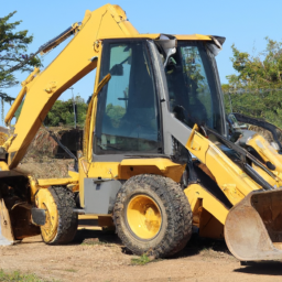
tand the tie rod end replacement process for a JCB Mini Excavator 8014 or 8016. Always refer to the specific service manual for detailed instructions and torque specifications.
      A seatbelt retractor is a crucial safety component found in vehicles, designed to manage the seatbelt’s tension and ensure optimal restraint for passengers during a collision or sudden stop. This device is responsible for winding and unwinding the seatbelt webbing, allowing it to extend when the occupant enters the vehicle and retract when not in use. The retractor mechanism is typically housed within a compact casing, often mounted on the vehicle’s floor or side pillar, ensuring that it is easily accessible while remaining out of the way.

      The primary function of the seatbelt retractor is to lock the seatbelt in place during a crash. Most retractors use a combination of a spring mechanism and an inertia-sensitive locking system. When the vehicle experiences rapid deceleration or an abrupt change in direction, the inertia mechanism engages, locking the seatbelt in place to prevent the occupant from moving forward. This locking feature is vital for reducing the risk of injury by keeping the passenger securely in their seat.

      Additionally, modern seatbelt retractors may incorporate advanced features such as pretensioners, which tighten the belt upon impact, further minimizing slack and maximizing the effectiveness of the restraint system. Overall, the seatbelt retractor plays a pivotal role in automotive safety, contributing to the protection of passengers and reducing the severity of injuries in accidents. Its reliable operation is essential for ensuring that seatbelts function as intended, delivering a critical layer of safety in vehicles.