Download Doosan Daewoo DX30Z Track Excavator Service Manual –

owners manual
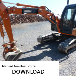
Repairing the gear shift linkage on a Doosan Daewoo DX30Z Track Excavator involves several steps. click here for more details on the download manual…..


    Daewoo Doosan Final Drive Motors – Excavator Travel Traction Motors http://www.finaldrivemotors.com/Daewoo-Travel-Motors-s/114.htm Daewoo Doosan Travel Motors – Daewoo Doosan Final Drive …

Here’s a reverse order breakdown of the process:

### 6. Reassemble the Excavator
– **Reattach any covers or panels** that were removed to access the gear shift linkage.
– **Reconnect the battery** and ensure all electrical connections are secure.
– **Lower the excavator to the ground** and perform a final inspection to ensure everything is in place.

### 5. Test the Gear Shift Mechanism
– **Start the excavator** and test the gear shift to ensure it operates smoothly.
– **Check for any unusual noises** or resistance while shifting gears.
– If everything functions correctly, the repair is successful.

### 4. Install the New or Repaired Linkage
– **Attach the new or repaired gear shift linkage** to the lever and the transmission.
ensure all bolts and fasteners are tightened to the manufacturer’s specifications.
– **Check alignment** to make sure the linkage is properly positioned.

### 3. Remove Defective Linkage
– **Disconnect the existing gear shift linkage** from the gear shift lever and the transmission.
– Take Note of how the linkage is connected for accurate reassembly.
– If applicable, **remove any retaining clips** or bolts that hold the linkage in place.

### 2. Inspect and Prepare
– **Inspect the gear shift linkage** for wear, damage, or misalignment. This may involve cleaning the area and checking for any broken components.
– If the linkage is damaged, determine whether it can be repaired or needs to be replaced.

### 1. Safety Precautions
– **Ensure the excavator is on a stable, level surface** and engage the parking brake.
– **Disconnect the battery** to prevent any electrical issues while working on the machine.
– Wear appropriate **personal protective equipment (PPE)** such as gloves
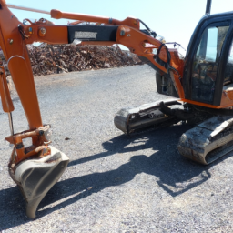
download Doosan Daewoo DX30Z Track Excavator workshop manual and safety glasses.

By following these steps in reverse order, you can effectively repair the gear shift linkage on a Doosan Daewoo DX30Z Track Excavator. Always refer to the specific service manual for detailed instructions and safety guidelines.
The side mirror, also known as a wing mirror or door mirror, is an essential component of a vehicle that plays a crucial role in ensuring safety and enhancing visibility while driving. Typically mounted on the outer edges of the vehicle, side mirrors are designed to provide the driver with a clear view of the areas adjacent to and behind the vehicle, which are often blind spots that are not visible through the rearview mirror.

Side mirrors come in various designs and features, including manual and power-adjustable types. Power-adjustable mirrors allow drivers to change the angle of the mirror using controls inside the vehicle, enhancing convenience and safety. Additionally, many modern vehicles are equipped with heated side mirrors to prevent fogging and ice accumulation in colder climates, thus maintaining visibility in adverse weather conditions.

Some advanced side mirrors include built-in turn signal indicators, which enhance visibility for other drivers and pedestrians by signaling lane changes or turns. Additionally, many vehicles now feature blind-spot monitoring systems that utilize sensors to alert drivers of vehicles in their blind spots, further increasing safety.

Side mirrors are typically constructed from durable materials, such as plastic and glass, designed to withstand various weather conditions and minor impacts. They are also subject to strict regulations regarding size, placement, and reflectivity to ensure they meet safety standards. Overall, side mirrors are vital for safe driving, providing essential information that helps drivers make informed decisions on the road.

Download 2014 BMW 530d xDrive (F11) LCI 5 Series Touring OEM Download Service & Repair Manual Software –

australian
Replacing the control arm on a BMW 530d xDrive F11 LCI Touring can be a challenging task, especially if you have limited mechanical experience. click here for more details on the download manual…..


    BMW 520d vs 530d vs 540d vs M550d ACCELERATION & TOP SPEED by AutoTopNL BMW 520d vs 530d vs 540d vs M550d ACCELERATION & TOP SPEED by AutoTopNL Subscribe to our channel to be the first to …

    How to replace bmw front shock absorber |how to install or replace front absorber on a bmw| how to fix a car engine misfire |how to fix a volkswagen with a misfire problem | @drcoolautofix how to replace a shock absorber …

Here’s a simplified guide to help you understand the process.

### What is a Control Arm?
The control arm is a crucial part of your car’s suspension system. It connects the wheel hub to the car’s frame and helps maintain proper wheel alignment while absorbing shocks from the road.

### Tools and Materials Needed:
1. **Basic Hand Tools**: Wrenches, sockets, and a ratchet.
2. **Jack and Jack Stands**: To lift the car safely.
3. **Pry Bar**: For leverage if needed.
4. **Torque Wrench**: To ensure bolts are tightened to the correct specification.
5. **Replacement Control Arm**: Make sure it’s compatible with your specific BMW model.
6. **Safety Gear**: Gloves and safety glasses.

### Steps for Control Arm Replacement:

#### 1. **Preparation**:
– **Park Safely**: Find a flat, stable surface to work on. Turn off the engine and engage the parking brake.
– **Gather Tools**: Have all your tools and replacement parts ready before you start.

#### 2. **Lift the Car**:
– Use the jack to lift the front of the car, then securely place jack stands underneath to support it. Never work under a car supported only by a jack.

#### 3. **Remove the Wheel**:
– Use a wrench or socket to loosen the lug nuts on the wheel you’re working on. Once loose, remove the wheel to expose the suspension components.

#### 4. **Locate the Control Arm**:
– The control arm is typically a curved metal arm that connects the wheel assembly to the vehicle chassis. It will have bushings at both ends.

#### 5. **Disconnect the Control Arm**:
– **Remove Bolts**: Use the appropriate socket to remove the bolts that connect the control arm to the chassis and the wheel hub. You might need to use a pry bar to help separate the parts if they are stuck.
– **Take Note of the Orientation**: Before fully removing the control arm, take a picture or note how everything is positioned to help with installation.

#### 6. **Install the New Control Arm**:
position the new control arm in the same orientation as the old one. Insert the bolts and hand-tighten them first.
– **Torque the Bolts**: Using a torque wrench, tighten the bolts to the manufacturer’s specified torque setting (this can usually be found in a repair manual or online).

#### 7. **Reattach the Wheel**:
– Place the wheel back onto the hub and hand-tighten the lug nuts. Once the car is back on the ground, you can fully tighten them.

#### 8. **Lower the Car**:
– Carefully remove the jack sdownload BMW 530d xDrive F11 LCI 5 Touring OEM workshop manualtands and lower the car back to the ground using the jack.

#### 9. **Test Drive**:
– After replacing the control arm, take the car for a short test drive to ensure everything feels right. Listen for any unusual noises or issues.

### Important Tips:
– **Work Slowly**: Don’t rush the process; take your time to ensure everything is done correctly.
– **Consult a Professional**: If at any point you feel uncomfortable or unsure, it’s wise to consult a professional mechanic.
– **Alignment**: After replacing suspension components like control arms, it’s recommended to have a wheel alignment performed to ensure proper handling and tire wear.

Remember, safety is paramount. If you’re not confident in your ability to perform this replacement, it’s best to seek help from a professional mechanic.
A turbocharger is an essential component in modern internal combustion engines, designed to enhance engine efficiency and performance by increasing the engine’s intake air density. It operates on the principle of forced induction, utilizing the exhaust gases produced during combustion to drive a turbine, which in turn compresses the incoming air before it enters the engine’s cylinders.

The turbocharger consists of two main parts: the turbine and the compressor. The turbine is connected to the exhaust manifold. As exhaust gases exit the engine, they spin the turbine wheel, which is connected to a shaft that also drives the compressor wheel. The compressor, located at the intake side of the engine, draws in ambient air, compresses it, and then sends it into the engine’s combustion chamber at a higher pressure. This increased air density allows for more fuel to be combusted, resulting in greater power output without significantly increasing the engine’s size or weight.

Turbochargers are particularly beneficial for improving fuel efficiency, as they enable smaller engines to produce power levels comparable to larger engines. However, they can also introduce complexities, such as turbo lag, which is the delay between the driver pressing the accelerator and the turbocharger delivering increased power. Advances in technology, such as variable geometry turbochargers and twin-scroll designs, have been developed to mitigate these issues, making turbocharging an increasingly popular choice in both performance vehicles and everyday cars. Overall, turbochargers play a pivotal role in meeting modern demands for power and efficiency in the automotive industry.

Download 2013 Mercedes-Benz S-Class S500 L BlueEFFICIENCY (W221) 4MATIC OEM Download Service & Repair Manual Software –

service
Replacing the gearbox (transmission) on a Mercedes-Benz S-Class S500 L BlueEFFICIENCY W221 4MATIC is a complex task that requires mechanical knowledge, specialized tools, and safety precautions. click here for more details on the download manual…..


    Buying a used Mercedes S-class (W221) – 2006-2013, Ultimate Buying Guide with Common Issues https://differentcarreview.com/2020/02/14/mercedes-s-class-w221/ Buying a used Mercedes Benz S-class (W221) – produced from …

    Top Gear – Mercedes-Benz W221 S-clas S500 REVIEW part 2

Below is a detailed description of the process, components involved, and the tools required.

### Components Involved

1. **Transmission (Gearbox)**: The automatic transmission unit that controls the power delivered from the engine to the wheels.
2. **Transmission Oil**: Necessary for lubrication and cooling of the transmission components.
3. **Transmission Mounts**: Rubber mounts that secure the transmission to the vehicle chassis.
4. **Driveshaft**: connects the transmission to the rear differential (for 4MATIC versions).
5. **Torque Converter**: Coupling between the engine and the transmission.
6. **Transmission Fluid Cooler**: Cools the transmission fluid.
7. **Particular Bolts and Fasteners**: Specific to the transmission unit.
8. **Transmission Filter and Gasket**: For the oil pan assembly during reinstallation.
9. **Electrical Connectors and Sensors**: Including the transmission control module (TCM) connections.
10. **Shifter Cable/Linkage**: connects the gear shift lever to the transmission.

### Tools Required

1. **Basic Hand Tools**: Wrenches, sockets, screwdrivers.
2. **Torque Wrench**: To ensure bolts are tightened to specified torque.
3. **Jack and Jack Stands**: To Safely lift and support the vehicle.
4. **Transmission Jack**: A specialized jack for securing and lifting the transmission.
5. **Oil Drain Pan**: To catch old transmission fluid.
6. **Pliers**: For removing clamps and connectors.
7. **Sealant**: For reassembling certain components.
8. **Service Manual**: For specific torque values and detailed procedures.

### Steps for Gearbox Replacement

1. **Preparation**:
– **Safety First**: Park the vehicle on a level surface, engage the parking brake, and disconnect the battery.
– **Remove the Underbody Covers**: If applicable, to access the transmission.

2. **Drain Transmission Fluid**:
– Place an oil drain pan underneath the transmission.
– Remove the transmission pan bolts and allow the fluid to drain completely.

3. **Remove Driveshaft**:
– Unbolt the driveshaft from the rear differential and transmission. Use a marker to note the position for reinstallation.
– Carefully remove the driveshaft and set it aside.

4. **Disconnect Transmission Cooler Lines**:
– Locate the transmission cooler lines and carefully disconnect them, allowing any remaining fluid to drain into the pan.

5. **Remove shifter Cable/Linkage**:
– Disconnect the shifter cable from the transmission. This may require removing a retaining clip.

6. **Support the Transmission**:
– Use a transmission jack to support the transmission. Ensure it is securely in place.

7. **Unbolt the Transmission**:
– Remove the mounting bolts connecting the transmission to the engine. These may be located on the bell housing and the transmission mounts.

8. **Remove Torque Converter Bolts**:
– If accessible, unbolt the torque converter from the flexplate.

9. **Lower the Transmission**:
– Carefully lower the transmission using the transmission jack, tilting it as necessary to clear the engine and transmission mounts.

10. **Remove the Old Transmission**:
– Once clear, carefully slide the transmission out from under the vehicle.

### Installation of the New Transmission

1. **Prepare New Transmission**:
– Before installation, ensure that the new transmission is compatibledownload Mercedes Benz S Class S500 L BlueEFFICIENCY W221 4MATIC OEM workshop manual and ready for installation. Replace the transmission filter and gasket if required.

2. **Align and Lift New Transmission**:
– Using the transmission jack, align the new transmission with the engine and carefully lift it into place.

3. **Bolt Transmission to Engine**:
– Reinstall all the transmission bolts to attach it securely to the engine. Refer to the service manual for the correct torque specifications.

4. **Reattach Torque Converter**:
– Bolt the torque converter to the flexplate.

5. **Reconnect shifter Cable/Linkage**:
– Reattach the shifter cable to the transmission.

6. **Reinstall Driveshaft**:
– Position the driveshaft back into place and secure it to the transmission and differential.

7. **Reconnect Cooler Lines**:
– Reattach the transmission cooler lines, ensuring they are securely tightened.

8. **Install Transmission Mounts**:
– Secure the transmission mounts back to the vehicle.

9. **Refill Transmission Fluid**:
– Once everything is reattached, refill the transmission with the appropriate type and amount of fluid.

10. **Reconnect Battery**:
– Reconnect the battery and check all electrical connections.

11. **Test Drive**:
– Start the vehicle and allow it to run. Check for any leaks and ensure the transmission shifts through all gears properly.

### Final Notes

– Always refer to the vehicle’s service manual for specific torque specifications and any additional steps unique to the W221 model.
– It is advisable to have a second person assist during the removal and installation of the transmission due to its weight and complexity.
– If unsure, consider consulting a professional mechanic for this procedure.

Performing a gearbox replacement is an advanced task and requires significant automotive knowledge. Always prioritize safety and ensure proper handling of tools and equipment.
The heater core is a crucial component of a vehicle’s heating system, playing a significant role in providing comfort to passengers, particularly during cold weather. It is essentially a small radiator that is located inside the cabin of the vehicle, typically behind the dashboard. The primary function of the heater core is to transfer heat from the engine’s coolant to the air that is blown into the cabin by the vehicle’s ventilation system.

When the engine runs, it generates heat, which is absorbed by the coolant circulating through the engine and then directed toward the heater core. As the hot coolant flows through the core, it heats up the metal fins or tubes of the heater core. A fan then blows air over these heated surfaces, effectively warming the air before it enters the cabin. This allows occupants to enjoy a comfortable environment regardless of external temperatures.

In addition to providing warmth, the heater core also plays a role in defrosting the windshield by directing warm air toward it, helping to clear condensation and ice. However, problems can arise with the heater core, such as leaks, which may lead to coolant loss and can create a foggy windshield or unpleasant odors in the cabin. Regular maintenance of the cooling system is essential to ensure the heater core functions effectively and to prevent any potential issues.

Download Karmann Ghia 1966 Repair Service Manual –

bookstore
Repairing the shift interlock on a Karmann Ghia can seem daunting, but with a step-by-step approach, you can tackle it even if you have little mechanical experience. click here for more details on the download manual…..


    Karmann Ghia, Shelby, Classic Cars, and More at Pistons at the Park, Austin Austin’s Pistons at the Park 16231 N Interstate Hwy 35, Pflugerville, TX 78660 https://pistonsatthepark.com/ Music: Busy Beat by …

    Auction VW Karmann Ghia – Worth Restoring? I came across this Classic VW Karmann Ghia while walking around a vehicle auction. In this video we’ll take a look at the car.

The shift interlock is a safety feature that prevents you from shifting out of “Park” without pressing the brake pedal. Here’s a simple guide to help you through the process.

### tools and Materials Needed:
– Screwdriver set (flathead and Phillips)
– Pliers
– Socket wrench set
– Replacement parts (if necessary)
– Flashlight (for better visibility)

### Safety First:
1. **Disconnect the Battery**: Before starting any repairs, disconnect the negative terminal of the battery to ensure safety.

### Step-by-Step Guide:

1. **Identify the Problem**:
– Ensure that the issue is indeed with the shift interlock. If the car won’t shift out of “Park,” it could be due to a faulty brake switch or the interlock mechanism.

2. **Remove the Center Console**:
– Use a screwdriver to remove any screws or clips holding the center console in place. This may include screws at the back or underneath.
– Carefully lift the console to expose the shift lever and the interlock mechanism. Be gentle to avoid breaking any plastic clips.

3. **Inspect the shift Interlock Mechanism**:
– Locate the shift interlock mechanism, which is typically found under the shift lever.
– Look for any broken or disconnected parts. If the mechanism seems jammed, it may just need some lubrication or adjustment.

4. **Check the Brake Light Switch**:
– The shift interlock system is connected to the brake light switch. If this switch is faulty, it may prevent the shift interlock from functioning properly.
– Locate the brake light switch, which is usually near the brake pedal. Make sure it’s securely connected and working. You can test it by pressing the brake pedal and checking if the brake lights turn on.

5. **Repair or Replace Parts**:
– If you find any broken parts in the shift interlock mechanism, you may need to replace them. Check with an auto parts store or online for compatible replacement parts.
– If lubrication is needed, use a small amount of suitable lubricant on moving parts to help them function smoothly.

6. **Reassemble the Center Console**:
– Once everything is screws or clips you removed earlier.

7. **Reconnect the Battery**:
– Reattach the negative terminal of the battery and ensure it’s tight.

8. **Test the shift Interlock**:
– Start the car and see if the shift lever now moves out of “Park” when you press the brake pedal. Make sure everything works smoothly.

### Final Tips:
– Take your time and don’t rush through the process. If you’re unsure about any step, consult a repair manual or seek help from someone with more experience.
– Keep track of all screws and parts as you disassemble to make reassembly easier.

With patience and careful attention to detail, you should be able to repair the shift interlock on your Karmann Ghia. Good luck!
A door seal, also known as a door weatherstrip or door gasket, is an essential component of a vehicle that plays a vital role in ensuring the comfort, safety, and longevity of the automobile. Located around the perimeter of the car door frame, the door seal is typically made from flexible materials such as rubber or foam, which allow it to create a tight fit when the door is closed.

The primary function of the door seal is to prevent the intrusion of external elements, such as water, dust, wind, and noise, into the vehicle’s interior. This is crucial not only for maintaining a comfortable cabin environment but also for protecting sensitive electronic components and interior materials from damage caused by moisture and dirt. By effectively sealing the door, the door seal contributes to the vehicle’s overall insulation, leading to improved energy efficiency and reduced heating or cooling costs.

Additionally, door seals play a role in enhancing vehicle safety. They help ensure that the doors close securely, which is vital for passenger safety during travel. Over time, door seals can wear out due to exposure to the elements, UV radiation, and regular use, leading to leaks and increased cabin noise. Regular inspection and replacement of worn or damaged door seals are essential for maintaining the vehicle’s performance and comfort. Overall, the door seal is a small but significant component that contributes to the overall driving experience.

Download 1989-1991 Mazda RX-7 RX7 Workshop Service Repair Manual 1989 1990 1991 –

sale
Suspension alignment on a Mazda RX-7 involves adjusting the angles of the wheels to ensure that they are set to the manufacturer’s specifications. click here for more details on the download manual…..


    Why Rotary Engines Kinda Suck The RX-7, the RX-8 and the 787B race car all have something in common – the rotary engine. The famous spinny ‘Dorito’ holds a …

    V12 Zonda Swapped Mazda RX7 VS. Rotary? 👀 When I was at SEMA I ran into Gooichi Motors and their V12 powered Zonda Mazda RX7 nicknamed “Pistachio.” During my …

Proper alignment can improve handling, tire life, and overall driving performance. The RX-7, known for its unique rotary engine and lightweight design, has specific alignment requirements. Below is a detailed guide on how to perform suspension alignment on a Mazda RX-7, including the necessary tools, components, and steps involved.

### Tools and Equipment Needed

1. **Alignment Rack**: A specialized platform with adjustable arms to measure wheel angles.
2. **Camber Gauge**: To measure the camber angle of the wheels.
3. **Toe Plates**: For measuring toe angle adjustments.
4. **Caster Camber Gauge**: For measuring caster angles.
5. **Wrench Set**: For loosening and tightening suspension components.
6. **Jack and Jack Stands**: To lift the vehicle safely.
7. **Tire Pressure Gauge**: To ensure tires are inflated to proper pressures.
8. **Measuring Tape**: For checking distances and alignment specifications.
9. **Chalk or Marking Tool**: For marking tire positions if necessary.

### Components Involved in Suspension Alignment

1. **Camber**: The angle of the wheels in relation to the vertical axis. Positive camber means the top of the wheel is tilted outwards, while negative camber means it is tilted inwards.
2. **Caster**: The angle of the steering axis when viewed from the side of the vehicle. Positive caster means the steering axis tilts towards the rear of the vehicle.
3. **Toe**: The angle of the wheels in relation to the centerline of the vehicle when viewed from above. Toe-in means the front of the wheels is closer together than the rear, while toe-out means the opposite.
4. **Control Arms**: Components that connect the wheel hub to the chassis and allow for up-and-down movement.
5. **Tie Rods**: Adjust the toe angle and connect the steering rack to the wheels.
6. **Struts and Shocks**: Absorb road impacts and maintain wheel contact with the road.
7. **Bushings**: Rubber or polyurethane components that allow for movement while providing support.

### Steps to Perform Suspension Alignment

1. **Preparation**:
– **Park the Vehicle**: Ensure the Mazda RX-7 is parked on a flat, level surface.
– **Check Tire Pressure**: Ensure all tires are inflated to the recommended pressure (usually found on the driver’s door jamb).
– **Inspect Suspension Components**: Before alignment, check for any worn or damaged components (e.g., bushings, tie rods, control arms).

2. **Lift the Vehicle**:
– Use a jack to lift the front of the vehicle and secure it with jack stands. Ensure the car is stable before proceeding.

3. **Initial Measurements**:
– Place the camber gauge on the wheel to measure the current camber angle. Record these measurements.
– Use toe plates to measure the toe angle by placing them against the front and rear edges of the tires and measuring the distance between them.

4. **Adjust Camber**:
– Locate the camber adjustment bolts on the strut assembly. Loosen these bolts slightly.
– Adjust the camber angle by tilting the top of the strut assembly inwards or outwards as needed. Tighten the bolts once the desired angle is achieved.
– Recheck the camber with the gauge.

5. **Adjust Caster**:
– Caster is typically adjusted by using offset bushings or adjustable control arms. If necessary, make these adjustments according to the specifications.
– Verify caster angles using the caster camber gauge.

6. **Adjust Toe**:
– Loosen the tie rod ends. Adjust the length of the tie rods to achieve the desired toe angle (in or out).
– Ensure that both sides are adjusted equally to maintain straight tracking.
– Re-measure using the toe platesdownload Mazda RX 7 RX7 workshop manual and make further adjustments as necessary.

7. **Final Checks**:
– Double-check all adjustments made. Ensure all bolts are tightened to the manufacturer’s specifications.
– Lower the vehicle back to the ground.

8. **Test Drive**:
– Take the vehicle for a test drive to ensure it handles correctly and that there are no unusual noises or vibrations.

### Conclusion

Proper suspension alignment is crucial for the performance and safety of your Mazda RX-7. By following these detailed steps and using the correct tools, you can achieve a well-aligned suspension that enhances handling and prolongs tire life. always refer to a service manual for specific alignment specifications for your model year, as they may vary. If you’re unsure about any part of the process, it’s wise to consult with a professional mechanic or alignment specialist.
The exhaust manifold gasket is a crucial component in an internal combustion engine, serving as a seal between the exhaust manifold and the engine block. Its primary function is to prevent exhaust gases from leaking out of the exhaust system, ensuring that these gases are directed through the exhaust pipes and ultimately out of the vehicle. This component is typically made from materials that can withstand high temperatures and corrosive substances, such as graphite, metal, or composite materials.

When an engine operates, it generates a significant amount of heat, and the exhaust manifold gasket must endure these extreme conditions. Over time, exposure to heat, pressure, and vibration can cause the gasket to degrade or fail, leading to various issues. A blown or damaged gasket can result in exhaust leaks, which may cause a noticeable decrease in engine performance, increased emissions, and a rise in fuel consumption. Moreover, an exhaust leak can produce a loud, unpleasant noise and may even lead to harmful exhaust fumes entering the vehicle cabin, posing safety risks to occupants.

Replacing an exhaust manifold gasket typically involves a labor-intensive process, as it requires the removal of the exhaust manifold. regular inspections and timely replacement of this component are essential for maintaining optimal engine performance and ensuring the longevity of the exhaust system. Proper installation and the use of high-quality gaskets can help mitigate future issues and enhance overall vehicle reliability.

Download Chevrolet Chevy Malibu Complete Workshop Service Repair Manual 2008 2009 2010 –

service
Tire rotation is an essential maintenance procedure that helps ensure even tire wear, extends the lifespan of the tires, and promotes better handling and safety. click here for more details on the download manual…..


    2019 Chevrolet Malibu Maintenance Reset Quick and simple. Let’s begin!

    Chevrolet Malibu – rust fixed at home

Here’s a detailed guide on how to perform a tire rotation on a Chevrolet Chevy Malibu, including the necessary tools and components.

### Components and Tools Needed:

1. **Tools:**
– **Lug Wrench:** A tool used to loosen and tighten the lug nuts on the wheels.
– **Jack:** A hydraulic or mechanical jack to lift the vehicle off the ground.
– **Jack Stands:** To support the vehicle once it is lifted and ensure safety.
– **Tire Pressure Gauge:** To check the tire pressure after rotation.
– **Torque Wrench:** To ensure lug nuts are tightened to the manufacturer’s specifications.
– **Work Gloves:** Optional for hand protection.

2. **Safety Equipment:**
– **Safety Glasses:** To protect your eyes from debris.
– **Wheel Chocks:** To prevent the vehicle from rolling while it’s lifted.

### Steps for Tire Rotation:

1. **Preparation:**
– **Park the Vehicle:** Ensure the car is on a flat, stable surface. Engage the parking brake to prevent the vehicle from rolling.
– **Gather Tools:** Have all your tools ready and within reach.

2. **Check Tire Pressure:**
– Before you begin the rotation, check the tire pressure using a tire pressure gauge. Ensure they match the recommended specifications listed in the owner’s manual or the sticker inside the driver’s door frame.

3. **Loosen lug Nuts:**
– Using the lug wrench, slightly loosen (but do not remove) the lug nuts on all four wheels. This is easier to do while the tires are still on the ground.

4. **Lift the Vehicle:**
– Use the jack to lift one side of the vehicle at a time. If using a floor jack, place it under the vehicle’s designated jacking point (usually located near the front or rear tires).
– Once the vehicle is lifted, place jack stands under the vehicle at secure points to support it safely.

5. **Remove the Wheels:**
– Remove the loosened lug nuts completely and take off the wheels. Keep the lug nuts in a safe place to avoid losing them.

6. **Rotate the Tires:**
– The recommended tire rotation pattern for a Chevrolet Chevy Malibu typically follows one of these patterns:
– **Front-to-Rear Rotation:** Move the front tires straight back to the rear, and the rear tires straight forward to the front.
– **Cross Rotation:** Move the front tires to the opposite sides of the rear (i.e., the front left to the rear right and the front right to the rear left) while moving the rear tires straight forward.
– If your Malibu has directional tires, ensure they remain on the same side of the vehicle.

7. **Reinstall the Wheels:**
– Place the wheels back onto the hubs and hand-tighten the lug nuts onto the wheel bolts. Ensure the wheel is seated properly against the hub.

8. **Tighten lug Nuts:**
– Using the lug wrench, tighten the lug nuts in a crisscross pattern to ensure even pressure. Don’t fully torque them yet; just make sure they are snug.

9. **Lower the Vehicle:**
– Carefully lower the vehicle back to the ground using the jack. Once the vehicle is fully on the ground, remove the jack sdownload Chevrolet Chevy Malibu workshop manualtands.

10. **Final Torque:**
– With the vehicle on the ground, use a torque wrench to tighten the lug nuts to the manufacturer’s recommended torque specification (usually found in the owner’s manual or on a sticker in the door jamb). This is crucial to prevent the lug nuts from loosening while driving.

11. **Check Tire Pressure Again:**
– After the rotation, check the tire pressure again and adjust it if necessary.

12. **Clean Up:**
– Store all tools and equipment away, and ensure the work area is clean.

### Maintenance Tips:
– Check the owner’s manual for the recommended tire rotation interval, which is typically every 5,000 to 7,500 miles.
– Inspect the tires for any signs of damage, uneven wear, or other issues during the rotation process.
– Consider having your alignment checked if you notice uneven tire wear after rotation.

Performing a tire rotation on your Chevy Malibu is a straightforward task that can be done at home with the right tools and precautions. Regular rotations will help maintain your vehicle’s performance and safety.
The brake master cylinder cap is an essential component of a vehicle’s braking system, designed to provide a secure seal for the brake fluid reservoir housed within the brake master cylinder. This cap serves multiple critical functions that are vital for the safe and efficient operation of the brakes.

Firstly, the brake master cylinder cap prevents contamination of the brake fluid by keeping out dirt, moisture, and other foreign particles. Contaminated brake fluid can lead to corrosion and degradation of the braking components, potentially compromising braking performance and safety. The cap typically features a rubber gasket or seal that ensures a tight fit, minimizing the risk of external debris entering the reservoir.

Secondly, the cap plays a crucial role in maintaining the appropriate pressure within the braking system. As the brake fluid is subjected to changes in temperature and pressure, the cap allows for minor expansions and contractions, preventing fluid leaks while maintaining an optimal environment for braking performance. This is particularly important because brake fluid is hygroscopic, meaning it absorbs moisture from the air. A well-sealed cap helps to minimize this absorption, preserving the integrity of the fluid over time.

Additionally, many brake master cylinder caps come equipped with a warning indicator or venting mechanism. This feature alerts the driver to low brake fluid levels or potential issues within the braking system, prompting necessary maintenance or inspections. Overall, the brake master cylinder cap may appear to be a simple component, but its role is vital in ensuring the reliability and safety of a vehicle’s braking system. Regular inspection and maintenance of the cap and the brake fluid reservoir are essential for optimal vehicle performance and safety.

Download Mazda 626 Station Wagon 1998 Repair Service Manual –

repairs
Repairing a starter motor on a Mazda 626 Station Wagon can be a detailed process. click here for more details on the download manual…..


    MAZDA 626 III Station Wagon (GV)

    How to Diagnose and Replace a Starter Learn how to diagnose and replace a starter in your car or truck. In this video I show you the common causes of a car that doesn’t …

Here’s a reverse-order breakdown of the steps involved in the repair:

### 7. Reconnect the Battery
– Once the starter motor is reassembled and secured in place, reconnect the negative (-) terminal of the battery.

### 6. Reinstall the starter Motor
– Position the starter motor back into its housing. Ensure it aligns properly with the mounting holes.
– Secure it in place with the bolts you previously removed. Tighten them to the manufacturer’s specified torque.

### 5. Reassemble the starter Components
– If you disassembled the starter motor for inspection or cleaning, reassemble the internal components (like brushes, armature, and solenoid) according to the repair manual.
make sure all parts are clean and in good working order.

### 4. test the starter Motor
– Before fully reinstalling, it’s a good idea to test the starter motor using a multimeter. Check for continuity and ensure it operates correctly when powered.

### 3. remove the Old starter Motor
– Disconnect any electrical connections to the starter motor, such as the solenoid wire and the main power cable.
– Unscrew and remove the mounting bolts holding the starter motor in place. Carefully slide the starter motor out.

### 2. Prepare the Work Area
make sure you have the necessary tools (wrenches, sockets, etc.)download Mazda 626 Station Wagon workshop manual and a clean work area to perform the repair.
– Ensure the vehicle is on a flat surface and the ignition is off.

### 1. Safety Precautions
– Before starting any work, ensure the vehicle is in park (or neutral) with the parking brake engaged.
– Wear safety goggles and gloves to protect yourself from potential debris or electrical hazards.

By following these steps in reverse order, you can ensure a methodical approach to repairing the starter motor on a Mazda 626 Station Wagon. Always refer to the vehicle’s service manual for specific details and torque specifications.
The brake rotor screw, often referred to as a brake rotor bolt or rotor retaining screw, is a crucial component in the braking system of a vehicle. This small yet essential fastener is responsible for securing the brake rotor to the wheel hub. The brake rotor, which is a disc-shaped component, plays a vital role in converting the kinetic energy of the moving vehicle into thermal energy through friction when the brakes are applied.

The brake rotor screw ensures that the rotor remains in place during the operation of the braking system. It is typically made of high-strength materials, such as steel or alloy, to withstand the significant forces and heat generated during braking. The design of these screws is such that they can handle the stress exerted by the brake calipers, which clamp down on the rotor to create friction.

Proper installation and torque specifications for brake rotor screws are critical, as loose or improperly secured rotors can lead to brake noise, reduced braking efficiency, and even rotor warping. Over time, these screws may become corroded or stripped, necessitating replacement to maintain optimal performance and safety. Overall, while often overlooked, the brake rotor screw is a fundamental component that contributes to the effectiveness and reliability of a vehicle’s braking system. Proper maintenance and attention to this component are essential for safe driving.

Download HARLEY DAVIDSON SHOVELHEADS 1966-1984Service Manual –

purchase
Overhauling the gear set on a Harley-Davidson Shovelhead engine involves several detailed steps, requiring a solid understanding of engine mechanics and the right tools. click here for more details on the download manual…..


    Shovelhead – Do It Yourself – Tune And Service Guide with Frank Kaisler This Full Length Film is Brought to you by Lowbrow Customs https://www.lowbrowcustoms.com In this instructional video, guru …

    Classic Harley Sound, Shovelhead with Drags

Below is a comprehensive guide to help you through the process. Please ensure you have the necessary skills and tools before attempting this overhaul, as improper handling can lead to severe engine damage.

### Tools and Materials Needed

1. **Basic Hand Tools**: Wrenches, sockets, screwdrivers, pliers, etc.
2. **Torque Wrench**: For accurate torque specifications.
3. **Impact Wrench**: Optional, but can make removing stubborn bolts easier.
4. **Gear Pullers**: For removing gears from shafts.
5. **Seal Puller**: For removing old seals.
6. **Clean Rags**: For cleaning surfaces and wiping down parts.
7. **Engine Oil**: For lubricating components during reassembly.
8. **Gasket Set**: New gaskets for reassembly.
9. **Replacement Gear Set**: If the current gears are worn beyond specifications.
10. **Assembly Lubricant**: For critical components during reassembly.

### Procedure to Overhaul the Gear Set

#### Step 1: Preparation

1. **Disconnect the Battery**: Remove the negative terminal to prevent any electrical shorts.
2. **Drain the Oil**: Remove the oil drain plug and allow the engine oil to fully drain into a suitable container.

#### Step 2: Remove the Primary Drive

1. **Remove the Primary Cover**: Unbolt the primary cover using a socket wrench. Carefully pry it off, ensuring not to damage the gasket.
2. **Remove the Clutch Assembly**: Take off the clutch pressure plate, springs, and friction/disc plates. Use a clutch holder tool if necessary to prevent the assembly from turning.
3. **Remove the Primary Chain**: Disconnect the chain from the front and rear sprockets. Ensure the chain is clean before storage.
4. **Remove the Chaincase**: Remove the bolts securing the chaincase and gently pry it off. Take care not to damage the gasket.

#### Step 3: Remove the Transmission

1. **Disconnect the Shifter Mechanism**: Unbolt the shifter and linkage. Note the position for reinstallation.
2. **Remove the Transmission Mount Bolts**: Unbolt the transmission from its mounting points. Support it as you remove the last bolts to prevent it from dropping.
3. **Disconnect the Output Shaft**: Remove the output shaft nut using a socket wrench. You may need to lock the shaft in place using a special tool.
4. **Remove the Transmission**: Carefully slide the transmission out of the frame.

#### Step 4: Disassemble the Transmission

1. **Remove the End Cover**: Unbolt the end cover from the transmission case. Take care of any internal components that may fall out.
2. **Take Out the Gears and Shafts**: Remove the gears from the main and counter shafts using gear pullers if necessary. Keep track of the order and orientation of all components.

#### Step 5: Inspect Components

1. **Check Gears**: Look for wear, pitting, or damage. Use a micrometer to measure the gears against specifications.
2. **Inspect Bearings**: Check the bearings for wear or damage. Spin them to feel for roughness.
3. **Inspect Seals and Gaskets**: Replace any worn seals or gaskets.

#### Step 6: Replace Gears (if necessary)

1. **Install New Gears**: If you have decided to replace the gears, ensure they are aligned properly on the shafts and press them on carefully.

#### Step 7: Reassemble the Transmission

1. **Install Shafts and Gears**: Place the main and counter shafts back into their respective positions within the transmission case, ensuring they are properly seated.
2. **Install the End Cover**: Bolt the end cover back onto the transmission case, ensuring a proper seal.
3. **Torque Fasteners**: Use a torque wrench to tighten all bolts to the appropriate specifications as listed in the service manual.

#### Step 8: Reinstall the Transmission

1. **Position the Transmission**: Carefully slide the transmission back into its mounting location in the frame.
2. **Reconnect the Output Shaft**: Install the output shaft nutdownload HARLEY DAVIDSON SHOVELHEADS workshop manual and secure it properly.
3. **Reconnect the Shifter Mechanism**: Reattach the shifter linkage to the transmission.

#### Step 9: Reinstall the Primary Drive

1. **Reattach the Chaincase**: Install the chaincase back onto the primary drive, ensuring a new gasket is in place.
2. **Install the Primary Chain**: Reconnect the chain to the front and rear sprockets.
3. **Reinstall the Clutch Assembly**: Place the clutch plates back in order, followed by the pressure plate and springs.
4. **Reattach the Primary Cover**: Bolt the primary cover back on, ensuring a proper seal.

#### Step 10: Final Steps

1. **Refill with Oil**: Pour in the appropriate type and amount of oil into the primary chaincase.
2. **Reconnect the Battery**: Reattach the negative terminal of the battery.
3. **Start the Engine**: Run the engine for a few minutes to check for unusual noises or leaks.

### Conclusion

Overhauling the gear set on a Harley-Davidson Shovelhead is a meticulous process requiring attention to detail. Ensure that all components are properly cleaned, inspected, and replaced as necessary. Always refer to a service manual specific to your bike for torque specifications and detailed diagrams. If you are unsure at any point, it’s advisable to consult with a professional mechanic to avoid potential damage.
The fan belt, also known as the serpentine belt or accessory belt, is an essential component in an internal combustion engine’s system. Its primary function is to drive various peripheral devices that are crucial for the engine’s operation and vehicle functionality. The fan belt typically connects the engine’s crankshaft to components such as the alternator, power steering pump, air conditioning compressor, and water pump.

Made from a durable rubber composite, the fan belt is designed to withstand the high temperatures and mechanical stresses present in an engine environment. The belt’s design often features grooves or ribs that help it grip the pulleys securely, ensuring efficient power transfer from the engine to the accessories.

Over time, fan belts can wear out due to factors such as heat, friction, and exposure to engine fluids. Signs of a failing fan belt may include squeaking or squealing noises, visible cracks or fraying on the belt surface, or a decrease in the performance of the driven accessories, such as dimming headlights or a malfunctioning air conditioning system.

Regular maintenance, including inspection and replacement of the fan belt, is crucial to prevent breakdowns and ensure the smooth operation of the vehicle. Neglecting to maintain the fan belt can lead to complete failure, resulting in significant engine damage and costly repairs.

Download HYUNDAI Crawler Excavator R300LC-7 Service Manual –

fix
Certainly! click here for more details on the download manual…..


    Vauxhall Meriva MPV review – CarBuyer Vauxhall Meriva MPV 2014 review: http://bit.ly/1hsu2al Subscribe to the Carbuyer YouTube channel: http://bit.ly/17k4fct Subscribe …

    Here’s a detailed guide on how to replace the radiator on a Hyundai Crawler Excavator R300LC-7, including descriptions of the tools you may need.

    ### Tools Required:
    – **Wrench Set**: A set of metric wrenches for loosening and tightening bolts and nuts.
    – **Socket Set**: A ratchet and socket set, preferably metric, for accessing tighter spaces.
    – **Pliers**: Adjustable or locking pliers for handling hoses and clips securely.
    – **Flathead and Phillips Screwdrivers**: For removing any screws that may hold panels or components in place.
    – **Radiator Hose Clamp Tool**: This tool makes it easier to remove and install hose clamps without damaging the hoses or clamps.
    – **Coolant Drain Pan**: To catch any coolant that spills when removing the radiator.
    – **Shop Towels or Rags**: For cleaning up spills and wiping down components.
    – **Torque Wrench**: To ensure that bolts are tightened to the manufacturer’s specified torque settings during reassembly.
    – **Safety Gear**: Gloves, goggles, and protective clothing to ensure safety during the process.

    ### Replacement Process:
    – **Preparation**:
    – Ensure the excavator is parked on a flat, stable surface.
    – Turn off the Engine and allow it to cool completely to avoid burns from hot components.

    – **Drain Coolant**:
    – Locate the drain valve on the bottom of the radiator.
    – Place the coolant drain pan beneath the valve and open it to drain the coolant.
    – Once drained, close the valve and dispose of the coolant properly.

    – **Remove Hoses**:
    – Identify and carefully remove the upper and lower radiator hoses using the radiator hose clamp tool or pliers.
    – Slide the clamps away from the hose ends and gently twist and pull the hoses off.

    – **Disconnect Electrical Connections**:
    – Identify any electrical sensors or fans connected to the radiator.
    – Carefully disconnect these connections, taking note of where each connection goes for easier reassembly.

    – **Unbolt Radiator**:
    – Use the wrench or socket set to remove bolts securing the radiator to the mounting brackets.
    – Be cautious of any additional brackets or supports that may need to be removed.

    – **Remove Radiator**:
    – After all connections and bolts are removed, carefully lift the radiator out of its compartment.
    – It may be helpful to have an assistant to help maneuver the radiator out to avoid damage.

    – **Inspect and Clean**:
    – Inspect the radiator mounting area for any debris or old sealant that may need to be cleaned.
    – Ensure that the new radiator fits properly in the space provided.

    – **Install New Radiator**:
    – Carefully position the new radiator in place, aligning it with the mounting brackets.
    – Reinstall and tighten the mounting bolts securely using the wrench or socket set.

    – **Reconnect Hoses**:
    – Reattach the upper and lower radiator hoses, ensuring they are seated properly.
    – Slide the clamps back into position and tighten them securely to prevent leaks.

    – **Reconnect Electrical Connections**:
    – Reconnect any electrical sensors, fans, or other components that were disconnected earlier, ensuring that each connection is secure.

    – **Refill Coolant**:
    – Open the radiator capdownload HYUNDAI Crawler Excavator R300LC 7 workshop manual and refill with the appropriate type and mixture of coolant.
    – Keep an eye on the overflow tank to ensure it is filled to the recommended level.

    – **Check for Leaks**:
    – Start the Engine and let it run for a few minutes while checking for any leaks around the hoses, clamps, and radiator.
    – Monitor the temperature gauge to ensure the system is functioning properly.

    – **Final Inspection**:
    – After confirming there are no leaks and the system is operating normally, double-check that all tools and materials have been removed from the work area.
    – Close the hood or access panels securely.

    – **Dispose of Old Radiator and Coolant**:
    – Properly dispose of the old radiator and any used coolant according to local regulations.

    ### Additional Tips:
    – Always consult the excavator’s service manual for specific instructions and torque specifications as they can vary by model.
    – If unsure about any step, consider consulting a professional mechanic to avoid damage to the machinery or personal injury.
    A blow-off valve (BOV) is a crucial component in turbocharged and supercharged engines, specifically designed to manage boost pressure and enhance Engine performance. Its primary function is to release excess pressure from the intake manifold when the throttle is closed, such as during gear shifts or rapid deceleration. When a driver suddenly removes their foot from the accelerator, the airflow intended for the Engine is abruptly cut off, causing a buildup of pressure in the intake system. If this pressure is not released, it can lead to compressor surge, which may damage the turbocharger and reduce its efficiency.

    The blow-off valve operates by opening to vent the excess pressure to the atmosphere or recirculating it back into the intake system, depending on the type of BOV used. There are two main types: atmospheric and recirculating. Atmospheric BOVs release the pressure into the environment, creating a distinctive “whoosh” sound that many car enthusiasts appreciate. In contrast, recirculating BOVs direct the vented air back into the intake before the turbocharger, helping maintain the boost pressure within the system and improving Engine response.

    In addition to protecting the turbocharger, the blow-off valve can also enhance Engine performance by ensuring smoother airflow, reducing turbo lag, and maintaining optimal boost levels. Overall, the BOV is an essential piece of hardware in performance tuning, contributing to both the longevity of the Engine components and the driving experience.

    Download 2014 VAUXHALL MERIVA B Service and Repair Manual –

    australia
    Certainly! click here for more details on the download manual…..


      Vauxhall Meriva MPV review – CarBuyer Vauxhall Meriva MPV 2014 review: http://bit.ly/1hsu2al Subscribe to the Carbuyer YouTube channel: http://bit.ly/17k4fct Subscribe …

      Battery & alternator health check Opel Vauxhall Meriva B. Voltage test multimeter. Winter che… Winter check. Battery & alternator health check opel meriva b. Voltage test with multimeter. Full tutorial on how to make sure your …

    Here’s a reverse order guide on how to perform power steering repair on a Vauxhall Meriva B. this guide assumes you have a basic understanding of automotive repair. Please ensure you have the proper tools and safety equipment before beginning any repair work.

    ### 6. Reassemble and Test
    – **Reconnect Battery**: Reattach the negative terminal of the battery.
    – **Fill Power Steering Fluid**: Check the power steering fluid reservoir and fill it to the appropriate level with the correct type of fluid.
    – **Start Engine**: Start the engine and let it idle. Turn the steering wheel from lock to lock several times to bleed the system of air.
    – **Check for Leaks**: Inspect all connections and hoses for any signs of leaks while the engine is running.
    – **Test Drive**: take the vehicle for a short test drive to ensure the power steering is functioning correctly.

    ### 5. Install New Components
    – **Install New Steering Rack/ Pump**: Position the new steering rack or pump in place and secure it with the necessary bolts.
    – **Connect Hoses**: Reconnect all hoses and ensure they are tightened properly. Use new O-rings if necessary.
    – **Reconnect Electrical Connectors**: If applicable, reconnect any electrical connectors to the power steering pump.

    ### 4. Remove Old Components
    – **Disconnect Hoses**: Using appropriate tools, disconnect the power steering hoses from the pump and rack. Be prepared for fluid spillage.
    – **Remove Steering Rack/Pump**: Unbolt the old steering rack or pump from its mounting points, and carefully remove it from the vehicle.
    – **Remove Any Obstructions**: Depending on the model, you may need to remove other components (like the engine splash shield or subframe) to access the steering components.

    ### 3. Prepare for Repair
    – **Lift Vehicle**: Safely lift the vehicle using jack stands or a hydraulic lift to access the steering components.
    – **Secure Workspace**: Ensure the area is clean and free of any obstacles.

    ### 2. Gather Tools and Replacement Parts
    – **Tools Needed**: Gather necessary tools such as wrenches, sockets, screwdrivers, pliers, and a fluid catch pan.
    – **Replacement Parts**: Obtain the necessary replacement parts (steering rack, power steering pump, hoses, or fluid) based on the diagnosis.

    ### 1. Diagnose the Problem
    – **Check Fluid Levels**: Start by checking the power steering fluid level, looking for leaks or signs of contamination.
    – **Inspect Components**: Inspect the power steering pump, steering rack,download VAUXHALL MERIVA B workshop manual and hoses for any signs of wear, leaks, or damage.
    – **Test Steering Function**: Turn the steering wheel to identify any unusual noises or resistance, which can indicate a problem with the power steering system.

    ### Safety Tips:
    – Always work in a well-ventilated area.
    – Use protective eyewear and gloves.
    – If unsure about any step, consult a professional mechanic or refer to a repair manual specific to the Vauxhall Meriva B.

    This reverse order guide outlines the steps involved in power steering repair. Always refer to the service manual for detailed instructions and specifications tailored to your vehicle model.
    Clear coat is a transparent layer of paint applied over the base color of a vehicle’s exterior to enhance its appearance and provide protection. Typically composed of acrylic or polyurethane resins, clear coat serves multiple vital functions in automotive finishes. Its primary role is to provide a glossy, high-shine finish that enhances the visual appeal of the car, making the colors appear more vibrant and deep. this glossy layer helps to create a smooth surface that reflects light effectively, giving the vehicle a polished look.

    In addition to aesthetic benefits, clear coat plays a critical role in protecting the underlying paint from environmental elements. It acts as a barrier against UV radiation, which can cause fading and oxidation over time. The clear coat also offers protection against other harmful factors such as harsh weather, bird droppings, tree sap, and road debris. By shielding the paint beneath, clear coat can significantly extend the lifespan of a vehicle’s finish, minimizing the need for frequent repainting.

    Moreover, clear coats can be formulated to include additional properties, such as scratch resistance and self-healing capabilities, further enhancing their protective qualities. However, it is essential to maintain the clear coat properly through regular washing and waxing to preserve its integrity and appearance. Overall, clear coat is a crucial element in automotive finishes, combining beauty and durability to keep vehicles looking their best for years.