Download JCB 406, 409 Wheel Loading Shovel Service Repair Manual –

buy
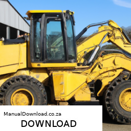
Adjusting the gear ratio on a JCB 406 or 409 Wheel Loading Shovel is a complex process that involves several steps and requires specialized tools and knowledge. click here for more details on the download manual…..


    How to operate your JCB Compact Wheel Loader For more information please follow the link below: https://www.jcb.com/en-gb/products/wheel-loaders Get to know your compact …

    2000 JCB 409B wheel loader for sale at auction | bidding closes May 7, 2019 View details and pictures — and place your bid at …

Here’s a detailed breakdown of the tools needed and the process involved:

### Tools Required:
– **Torque Wrench**:
– Used to apply a specific amount of torque to fasteners, ensuring they are tightened to the manufacturer’s specifications.

– **Socket Set**:
– A variety of sockets (including deep sockets) to fit different bolt sizes on the wheel loader. Ensures that you can access and remove the necessary components.

– **Wrenches**:
– Adjustable and fixed wrenches to handle various nuts and bolts that may not be accessible with sockets.

– **Pliers**:
– For gripping, twisting, and cutting any wiring or small components as needed during adjustment.

– **Screwdrivers**:
– Both flathead and Phillips to remove or adjust any covers or components that may obstruct access to the gear components.

– **Jack and Stands**:
– To safely lift and secure the wheel loader before beginning work on the undercarriage.

– **Oil Drain Pan**:
– For catching any fluids that may need to be drained during the adjustment process.

– **Measuring Tools**:
– Calipers or a micrometer to measure gear components for precision adjustments.

– **Service Manual**:
– The vehicle’s specific manual provides diagrams and specifications for gear ratios and adjustment procedures.

### Adjustment Process:
– **Safety First**:
– Engage the parking brake and ensure the machine is on a flat surface. Use wheel chocks for additional safety. Wear protective gear including gloves and safety glasses.

– **Prepare the Machine**:
– Use a jack to lift the front of the loader. Secure it with jack stands to prevent it from falling during the adjustment.

– **Drain Fluids**:
– If necessary, drain the transmission or differential fluid into an oil drain pan to prevent spills and make it easier to access the components.

– **Remove Covers**:
– Use screwdrivers and wrenches to remove any covers or shields that protect the gear assembly. This may include side panels or undercarriage covers.

– **Inspect current Gear Ratio**:
– Before making adjustments, measure the current gear ratio by checking the size of the gear teeth and their arrangement. compare these measurements with those provided in the service manual.

– **Adjust Gear Components**:
– Depending on the design, you might need to replace gears or adjust the alignment of the existing gears. This could involve loosening bolts with a torque wrench or socket and repositioning gears according to the desired ratio.

– **Reassemble Components**:
– Once adjustments are made, carefully reassemble any removed components. Use the torque wrench to ensure bolts are tightened to the manufacturer’s specifications.

– **Refill Fluids**:
– Refill the transmission or differential with the appropriate typedownload JCB 406 409 Wheel Loading Shovel workshop manual and amount of fluid, as specified in the service manual.

– **Test the Adjustment**:
– Start the machine and conduct a test run. Pay attention to how the machine operates under load to ensure the new gear ratio is functioning as intended.

– **Final Inspection**:
– After testing, inspect all components for any signs of leaks or abnormal wear. Ensure all tools are removed from the work area and that the machine is in a safe, operable condition.

### Conclusion:
Adjusting the gear ratio on a JCB 406 or 409 Wheel Loading Shovel requires careful attention to detail, the right tools, and a thorough understanding of the machinery. always refer to the manufacturer’s service manual for specific instructions and safety precautions. If uncertain, it’s advisable to consult with a professional technician.
The emission control valve is a critical component of a vehicle’s emission control system, which is designed to reduce the release of harmful pollutants into the atmosphere. This valve plays a significant role in managing the flow of gases and vapors from the fuel system and the engine, ensuring that emissions comply with regulatory standards.

Typically found in systems such as the Evaporative Emission Control System (EVAP), the emission control valve helps prevent the escape of fuel vapors from the fuel tank into the atmosphere. It operates by controlling the flow of these vapors to the engine, where they can be burned during the combustion process instead of being released into the environment. This not only helps reduce hydrocarbon emissions but also improves fuel efficiency.

The emission control valve can be electronically or mechanically operated. In modern vehicles, it is often controlled by the engine control unit (ECU), which monitors various parameters such as engine temperature and pressure to optimize performance. When the engine is running, the valve opens and closes at specific intervals, allowing for the effective recycling of fuel vapors and maintaining optimal air-fuel ratios.

Failure of the emission control valve can lead to increased emissions, reduced engine performance, and can trigger warning lights on the dashboard. Regular maintenance and timely replacement of a faulty valve are essential for ensuring compliance with environmental regulations and for the overall health of the vehicle’s engine.

Download New Holland 900W Operators Manual –

bookshop
Replacing the valve body on a Holland 900W s involves several steps that should be followed carefully to ensure proper installation and functionality. click here for more details on the download manual…..


    Mantenimiento a Generadores: Verificar el Aceite

    The Truth about FAT Tire Ebikes: Sidestep the Bullsh💩 https://tailhappytv.com click here to see my favorite ebikes ⚡️ The pitfalls and deception to look out for when buying a 750w …

Here’s a reverse order outline of the process:

### 8. Reassemble the Transmission
– **Reconnect Electrical Connections**: Reattach any electrical connectors that were disconnected during the removal process.
– **Reinstall the Transmission Pan**: Place a new gasket on the pan (if applicable) and bolt it back onto the transmission securely.
– **Fill Transmission Fluid**: Refill the transmission with the appropriate type and amount of fluid through the dipstick tube.

### 7. Install the New Valve Body
– **Position the New Valve Body**: Carefully align the new valve body with the transmission casing and gently lower it into place.
– **Secure the Valve Body**: Tighten all bolts to the manufacturer’s specifications to ensure a secure fit.

### 6. Remove the Old Valve Body
– **Disconnect Any Remaining Connections**: Ensure all hoses and electrical connectors are fully detached.
– **Unscrew the Bolts**: Remove all bolts securing the old valve body to the transmission.
– **Lift Out the Valve Body**: Carefully lift the old valve body out of the transmission casing.

### 5. Prepare for Removal
– **Drain Transmission Fluid**: Place a drain pan underneath and remove the drain plug or the transmission pan to allow fluid to drain out.
– **Disconnect the Battery**: Disconnect the negative terminal of the battery to prevent any electrical issues.

### 4. Access the Valve Body
– **Remove the Transmission Pan**: Unscrew and take off the transmission pan to expose the valve body.
– **Remove Any Obstructions**: Take off any components or brackets that might obstruct access to the valve body.

### 3. Safety Precautions
– **Gather Tools and Parts**: Collect necessary tools (socket set, torque wrench, etc.) and the new valve body.
– **Read the Service Manual**: Familiarize yourself with the specific instructions and torque specifications for your model.

### 2. Prepare the Workspace
– **Ensure a clean Area**: Work in a clean, organized space to avoid contamination.
– **Use Proper Safety Gear**: Wear gloves and safety glasses to protect yourself during the replacement process.

### 1. Assess the Situation
– **Diagnose the Issue**: Confirm that the valve body is indeed the problem by checking for symptoms like slipping, harsh shifting, or fluid leaks.

### Conclusion
Following these steps in reverse order can help you undersdownload Holland 900W s workshop manualtand the valve body replacement process on a Holland 900W s. Always refer to the specific service manual for detailed instructions and specifications related to your model for the best results. If you’re not experienced with auto repairs, consider consulting a professional mechanic.
A bumper is a crucial component of a vehicle’s structure, typically located at both the front and rear ends. Its primary function is to absorb impact during low-speed collisions, thereby protecting the more delicate parts of the vehicle, such as the engine, transmission, and other vital systems. Bumpers are designed to minimize damage to both the vehicle itself and any other objects or vehicles it may come into contact with.

Modern bumpers are usually constructed from a combination of materials, including plastic, rubber, and metal. This blend allows for a lightweight yet durable structure that can absorb energy during an impact. Many bumpers also incorporate energy-absorbing elements, such as foam or crumple zones, which further enhance their ability to mitigate damage. In addition to their protective role, bumpers often house various features, including sensors, lights, and towing attachments.

Moreover, bumpers play a significant role in a vehicle’s aesthetics and aerodynamics. Manufacturers often design them to align with the overall style of the vehicle, enhancing its visual appeal. In terms of regulations, bumpers must meet specific safety standards set by government agencies, ensuring they provide adequate protection in the event of a collision. Overall, bumpers are integral to a vehicle’s safety, functionality, and design, serving as the first line of defense in automotive safety.

Download 2004-2005 Subaru impreza WRX STI Service Repair Manual –

repair
Performing a transmission fluid pressure test on a Subaru Impreza WRX STI involves several steps and requires specific tools and equipment. click here for more details on the download manual…..


    Bader’s 17 STI vs 600whp+ C6 Vette 17 Sti takes down 600whp+ C6 Vette STI Mods -Built Motor -PTE 6870 Turbo -ETS Turbo Kit -ETS FMIC -Tuned on E98 -Medium …

    New wheel bearings and ARP studs for the Boostaholics GC8 RSTI Subaru Impreza Working on the Boostaholics GC8 seemed like it had become more of a lifestyle than something to do; there was that much work …

below is a detailed guide on how to conduct this test, including descriptions of the necessary components:

### Tools and Equipment Needed

1. **Transmission Pressure Gauge Kit**:
– A gauge that can measure hydraulic pressure, typically ranging from 0 to 300 PSI.
– Includes adapters for various transmission lines.

2. **Wrenches and Sockets**:
– Standard and metric wrenches for removing components.
– Ratchet and socket set for bolts.

3. **Screwdriver Set**:
– Flathead and Phillips screwdrivers for various fasteners.

4. **Pliers**:
– To remove clamps or hoses.

5. **Fluid Catch Pan**:
– A container to catch any fluid that may spill during the process.

6. **Transmission Fluid**:
– Ensure you have the correct type of fluid for your Subaru (typically Subaru ATF for automatic transmissions).

7. **Safety Gear**:
– Gloves, safety glasses, and possibly a face mask for protection against fluid.

### Preparation Steps

1. **Safety First**:
– Park the vehicle on a level surface and engage the parking brake. Ensure that the engine is off and cool before beginning.

2. **Gather Materials**:
– Have all tools and equipment ready and easily accessible.

3. **Lift the Vehicle**:
– If necessary, use a hydraulic jack to lift the front of the vehicle and secure it with jack stands to access the transmission area.

### Conducting the Pressure Test

1. **Locate the Transmission Test Port**:
– On the Subaru Impreza WRX STI, the test port is usually located on the transmission itself. Refer to the service manual for the exact location, as it may vary by year.

2. **Remove the Test Port Plug**:
– Use the appropriate wrench to carefully remove the test port plug. Be prepared for some fluid to spill out. Use a catch pan to collect any fluid.

3. **Install the Pressure Gauge**:
– Take the transmission pressure gauge and attach it to the test port. Ensure it is securely connected to avoid leaks.
– If necessary, use the appropriate adapter to make the connection.

4. **Start the Engine**:
– With the gauge connected, start the engine and allow it to idle. Make sure the vehicle is in park (for automatic transmissions) or neutral (for manual transmissions).

5. **Check Pressure Readings**:
– Observe the pressure gauge readings. You will typically want to check the pressure at various points:
– **Idle**: Note the pressure at idle. The typical range should be specified in the service manual.
– **In Gear**: Shift the transmission into gear (Drive or Reverse) and observe the pressure reading.
– **WOT (Wide Open Throttle)**: If specified, perform this test to measure pressure at full throttle.

6. **Compare Readings**:
– Compare the readings to the specifications in the service manual. Abnormal readings can indicate issues such as low fluid levels, pump problems, or internal leaks.

7. **Shut Off the Engine**:
– After taking the necessary readings, turn off the engine.

8. **Remove the Gauge**:
– Carefully unscrew the pressure gauge from the test port. Be cautious of any remaining fluid that may spill.

9. **Reinstall the Test Port Plug**:
– Use a new sealing washer if necessarydownload Subaru impreza WRX STI workshop manual and reinstall the test port plug securely.
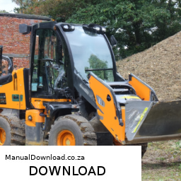
### Final Steps

1. **Check Fluid Level**:
– After the test, check the transmission fluid level. If any fluid was lost during the test, top it off using the correct type of transmission fluid.

2. **Inspect for Leaks**:
– Start the vehicle again and inspect the test port for any leaks.

3. **Lower the Vehicle**:
– If the vehicle was lifted, safely lower it back to the ground after ensuring all tools and equipment are removed from underneath.

### Conclusion

A transmission fluid pressure test helps diagnose potential transmission issues on a Subaru Impreza WRX STI. Properly interpreting the pressure readings is crucial for identifying problems. If you find any anomalies in the pressure readings, consult a professional mechanic or refer to the service manual for further diagnostic steps. Always follow safety precautions when working under the vehicle and handling transmission fluid.
Cruise control is an advanced automotive feature designed to enhance driving convenience and fuel efficiency during long-distance travel. It allows a vehicle to maintain a constant speed without the driver needing to keep their foot on the accelerator pedal. Typically activated by the driver, either via a button or a stalk on the steering wheel, cruise control engages once the vehicle reaches a desired speed, which can range from around 25 mph to the maximum speed limit of the vehicle.

Once activated, the system takes over the throttle control, adjusting the engine’s power output to maintain the set speed. This can significantly reduce fatigue during long drives, as the driver can relax their foot and maintain a more comfortable posture. Additionally, it promotes better fuel economy since maintaining a steady speed often leads to improved gas mileage compared to frequent acceleration and deceleration.

Modern vehicles often feature adaptive cruise control, which enhances traditional systems by incorporating radar and cameras to monitor traffic conditions. This advanced technology automatically adjusts the vehicle’s speed in response to slower-moving traffic, thereby improving safety by reducing the risk of collisions. Overall, cruise control is a practical and increasingly sophisticated component that contributes to the overall driving experience, making it safer and more enjoyable.

Download New Holland LS190 Skid Steer Loader Operators Owners Maintenance Manual –

discount
Overhauling the gear set on a Holland LS190 Skid Steer Loader can be a complex task, especially for someone with little mechanical experience. click here for more details on the download manual…..


    New Holland LS190 SkidSteer Operation Video Video showing the operation of the New Holland Skid Steer.

    New holland ls190 skid steer For sale.

However, I’ll break it down into simpler steps, explaining the process in a way that’s easier to understand. Before you start, ensure you have the right tools, safety equipment, and a service manual for reference.

### Tools and Materials Needed:
1. **Basic Hand Tools**: Wrenches, sockets, screwdrivers, pliers, etc.
2. **Torque Wrench**: To ensure bolts are tightened to the manufacturer’s specifications.
3. **Pry Bar**: For removing stubborn parts.
4. **Gear Oil**: To refill the gear set after overhaul.
5. **Cleaning Supplies**: Rags, brushes, and degreasers.
6. **Replacement Parts**: Gaskets, seals, bearings, and any worn gear components.

### Safety Precautions:
– **Wear Safety Gear**: Gloves, safety glasses, and steel-toed boots.
– **Work in a Well-Ventilated Area**: Preferably outdoors or in a garage with good airflow.
– **Disconnect the Battery**: To prevent accidental starts.

### Step-by-Step Overhaul Process:

1. **Preparation**:
– **Read the Manual**: Familiarize yourself with the machine and specific gear set components.
– **Gather Tools**: Ensure you have everything ready before starting.

2. **Drain the Gear Oil**:
– **Locate the Drain Plug**: This is usually at the bottom of the gear case.
– **Place a Container**: Position a container to catch the old oil as you remove the plug.
– **Remove the Plug**: Allow the oil to drain completely.

3. **Remove the Gear Set**:
– **Access the Gear Set**: This may involve removing panels or covers. Use your manual to identify how to access the gear set.
– **Disconnect Components**: Carefully disconnect any components that are in the way (like drive shafts or other attachments).
– **Unbolt the Gear Set**: Use the appropriate socket to remove the bolts holding the gear set in place. Keep track of where each bolt goes.

4. **Inspect and Clean**:
– **Check for Wear**: Look for any worn gears, bearings, or seals. If they are damaged, they will need to be replaced.
– **Clean Surfaces**: Use a degreaser and rags to clean the gear housing and any parts you will be reusing.

5. **Replace Worn Parts**:
– **Install New Gears/Seals**: Replace any worn components with new parts. Make sure they are fitted correctly.
– **Use Gasket Sealant**: If applicable, apply gasket sealant to ensure a good seal when reassembling.

6. **Reassemble the Gear Set**:
– **Position the Gear Set**: Carefully place the gear set back into the housing.
– **Secure with Bolts**: Reinstall and tighten all bolts to the specified torque in the manual.

7. **Refill with Gear Oil**:
– **Locate the Fill Plug**: find the fill plug on the gear case.
– **Pour in New Gear Oil**: Using a funnel, fill the case with new gear oil until it reaches the recommended level. Consult your manual for the specific typedownload Holland LS190 Skid Steer Loader s workshop manual and amount of oil.

8. **Final Checks**:
– **Inspect Everything**: Double-check all connections, bolts, and seals to ensure everything is secure.
– **Reconnect the Battery**: If you disconnected it earlier.

9. **Test the Loader**:
– **Start the Loader**: Turn on the skid steer and let it run for a few minutes.
– **Check for Leaks**: Look underneath for any signs of leaking oil and listen for unusual noises.

### Conclusion
Overhauling the gear set on a Holland LS190 Skid Steer Loader is a detailed process that requires careful attention to detail. If at any point you feel unsure, it’s wise to consult a professional mechanic or technician. Always refer to the service manual for specific instructions and specifications related to your machine. Good luck!
The windshield, also known as the windscreen in some regions, is a crucial component of a vehicle that serves multiple functions, primarily providing visibility and protection for the driver and passengers. Located at the front of the car, the windshield is made from laminated safety glass, which consists of two layers of glass with a layer of polyvinyl butyral (PVB) sandwiched in between. This construction not only enhances the strength of the glass but also prevents shattering upon impact, thereby reducing the risk of injury from flying glass shards in the event of an accident.

Beyond its protective role, the windshield contributes to the overall structural integrity of the vehicle. It aids in maintaining the shape of the car’s cabin and plays a vital role in the deployment of airbags during collisions. The design of modern windshields often incorporates features such as tinting for glare reduction, integrated heating elements to prevent frost and ice accumulation, and even advanced technologies like heads-up displays and sensors for advanced driver-assistance systems (ADAS).

Additionally, windshields are designed to improve aerodynamics, reducing drag and contributing to fuel efficiency. Regular maintenance, including the prompt repair of chips and cracks, is essential for ensuring optimal visibility and safety. Therefore, the windshield is not just a transparent barrier; it is an integral element of automotive engineering that enhances both safety and performance.

Download DODGE CARAVAN 2003 (+Diesel) Service Manual –

bookstore
Replacing the control arm on a Dodge Caravan may seem daunting if you have little mechanical experience, but with some basic tools and a little patience, you can do it! click here for more details on the download manual…..


    2012 Dodge Caravan V6 EXHAUST w/ MUFFLER DELETE! We could not find the black exhaust tips on Amazon. Below are black exhaust tips that are similar** WANT 4 INCH BLACK …

    How to Change Engine Oil 2008-2020 Dodge Grand Caravan Buy Now! New Engine Oil Filter from 1AAuto.com https://trq.video/ia-1AEEK00901 New Engine Oil Filter from 1AAuto.com …

Here’s a step-by-step guide to help you through the process:

### Tools and Materials Needed:
– Jack and jack stands
– Lug wrench
– Socket set
– Wrench set
– Pliers
– Hammer
– Replacement control arm
– Torque wrench (optional but recommended)
– Safety glasses and gloves

### Step-by-Step Guide:

#### 1. **Prepare Your Vehicle**
– **Safety First:** Park your Dodge Caravan on a flat surface and turn off the engine. Engage the parking brake.
– **Gather Tools:** Make sure you have all the tools and the new control arm ready.

#### 2. **Lift the Vehicle**
– **Loosen Lug Nuts:** Use the lug wrench to slightly loosen the lug nuts on the front wheels (do not remove them completely yet).
– **Jack Up the Vehicle:** Use the jack to lift the front of the vehicle. Once it’s elevated, place jack stands underneath for safety.
– **Remove the Wheels:** Now, completely remove the lug nuts and take off the front wheels.

#### 3. **Locate the Control Arm**
– The control arm is a metal arm connecting the wheel assembly to the vehicle frame. It’s usually located near the bottom of the vehicle’s suspension.

#### 4. **Remove Old Control Arm**
– **Disconnect the Ball Joint:** Use a socket and wrench to remove the nut that holds the ball joint to the control arm. you may need to use a hammer to gently tap the ball joint free if it’s stuck.
– **Remove Bolts:** Locate the bolts that secure the control arm to the vehicle frame and the steering knuckle. Use a socket and wrench to remove these bolts.
– **Take Out the Control Arm:** Once all bolts are removed, carefully take out the old control arm from the vehicle. Be mindful of any attached components.

#### 5. **Install the New Control Arm**
– **Position the New Control Arm:** place the new control arm into position in the same place as the old one.
– **Reattach Bolts:** Secure the control arm to the vehicle frame and the steering knuckle by threading the bolts back in. Make sure everything is aligned correctly.
– **Tighten the Bolts:** Use a torque wrench (if available) to tighten the bolts to the manufacturer’s specifications. If you don’t have a torque wrench, make sure they are tight but do not overtighten.

#### 6. **Reconnect the Ball Joint**
– Attach the ball joint to the control arm and secure it with the nut you removed earlier. Again, ensure it is tight.

#### 7. **Reinstall Wheels**
– Put the wheels back ondownload DODGE CARAVAN + workshop manual and hand-tighten the lug nuts.
– Lower the vehicle from the jack stands and then fully tighten the lug nuts with the vehicle on the ground.

#### 8. **Final Checks**
– Go through all the bolts and ensure everything is tight and secure.
check to make sure there are no tools or parts left under the vehicle.

#### 9. **Test Drive**
– Start the vehicle and take it for a short test drive to ensure everything is working properly. Pay attention to any unusual noises or handling issues.

### Conclusion
Replacing a control arm can be a manageable task with the right tools and a methodical approach. If you encounter any problems or feel unsure at any step, don’t hesitate to ask for help or consult a professional mechanic. Always prioritize safety!
The master cylinder is a crucial component of a vehicle’s hydraulic brake system, playing a vital role in ensuring effective and reliable braking performance. It is essentially a cylindrical container that houses brake fluid and serves as the starting point for the hydraulic force that activates the brakes. When a driver presses the brake pedal, the force is transmitted to the master cylinder, which then compresses the brake fluid inside it.

This compression generates hydraulic pressure, which travels through brake lines to the brake calipers or wheel cylinders at each wheel. As the hydraulic pressure builds up, it forces the brake pads against the rotors (in disc brakes) or the brake shoes against the drums (in drum brakes), thereby slowing down or stopping the vehicle. The master cylinder typically consists of different chambers—usually one for the front brakes and one for the rear brakes—allowing for independent operation and enhancing safety.

In modern vehicles, master cylinders can be equipped with additional features such as anti-lock braking systems (ABS) that help prevent wheel lockup during hard braking. Regular maintenance of the master cylinder is essential, as leaks or air bubbles in the brake fluid can lead to brake failure. Thus, understanding the function and importance of the master cylinder is critical for both vehicle safety and performance.

Download New Holland CE LB110.B, LB115.B, LB75.B, LB90.B Operators Manual –

bookshop
Replacing the trailing arm on a Holland CE LB110.B, LB115.B, LB75.B, or LB90.B involves several steps. click here for more details on the download manual…..


    2001 NEW HOLLAND LB90 For Sale http://http://www.machinerytrader.com/listingsdetail/detail.aspx?OHID=9889133 Title: 2001 NEW HOLLAND LB90 For Sale …

Here’s a reverse order breakdown of the process:

### 7. **Reassemble and Tighten Components:**
– Reinstall any removed components such as the wheel, brake drum, and hub.
– Tighten the wheel lug nuts to the manufacturer’s specified torque.
– Reattach any other parts that were removed during the process, ensuring everything is secure.

### 6. **Lower the Equipment:**
– Carefully lower the machine back to the ground using the hydraulic system or jack.
– Remove any jack stands or supports used for safety.

### 5. **Install the New Trailing Arm:**
– Position the new trailing arm in place, aligning it with the mounting points.
– Insert and hand-tighten the bolts or fasteners that secure the trailing arm.

### 4. **Secure the Trailing Arm:**
– Use a torque wrench to tighten the bolts to the manufacturer’s specified torque settings.
– Ensure that all fasteners are secure and that the trailing arm is properly installed.

### 3. **Remove the Old Trailing Arm:**
– Disconnect any components that may be attached to the trailing arm, such as brake lines or sensors.
– Unbolt the old trailing arm from its mounting points using appropriate tools.
– Carefully remove the old trailing arm from the equipment.

### 2. **Prepare for Installation:**
– Ensure the work area is clear and organized.
– Gather all necessary tools, including wrenches, sockets, a torque wrench, and any other specific tools required for your model.

### 1. **Safety Precautions:**
– Before starting, ensure that the equipment is on a flat surface and secured.
– Use wheel chocks to prevent movement.
– Wear appropriate personal protective equipment (PPE).

This reverse order provides a structured approach to replacing a trailing arm in Holdownload Holland CE LB110.B LB115.B LB75.B LB90.B s workshop manualland CE equipment models. Always refer to the specific service manual for detailed instructions and torque specifications for your particular model.
The water pump gasket is a crucial component in an engine’s cooling system, serving as a seal between the water pump and the engine block. Its primary function is to prevent coolant leaks, ensuring that the engine maintains the optimal operating temperature. The water pump circulates coolant through the engine and the radiator, facilitating heat dissipation. Without a properly functioning gasket, the coolant could escape, leading to overheating and potential engine damage.

Typically made from materials like rubber, cork, or composite substances, the water pump gasket is designed to withstand extreme temperatures and pressures within the engine environment. Over time, exposure to heat, coolant, and vibration can cause the gasket to deteriorate, leading to leaks. Symptoms of a failing water pump gasket might include visible coolant puddles beneath the vehicle, an overheating engine, or a drop in coolant levels without any apparent leaks elsewhere.

Replacing a worn or damaged water pump gasket is essential for maintaining the efficiency and longevity of the engine. The process usually involves draining the coolant, removing the water pump, cleaning the mating surfaces, and installing a new gasket before reassembling the components. Regular maintenance checks can help identify issues with the water pump gasket early, preventing more extensive damage and costly repairs. Properly functioning water pump gaskets contribute significantly to the overall health of the engine, making them an essential aspect of automotive care.

Download KOMATSU WB150AWS-2N BACKHOE Loader Operation & Maintenance Manual –

do your own repairs
Replacing the PCV (Positive Crankcase Ventilation) valve on a Komatsu WB150AWS 2N backhoe loader involves several steps. click here for more details on the download manual…..


    VW Volkswagen Eos Roof Seal Cleaning Access, Drain Line Location & Flushing Different service positions for cleaning the seals and drain lines as well as locations.

    Here’s a reverse order guide to help you understand the process from the last step back to the first:

    ### 7. Final Checks
    – **Reconnect the Battery**: If you disconnected the battery, reconnect it.
    – **Start the Engine**: Start the engine and let it idle. check for any leaks or unusual noises.
    – **Inspect Functionality**: Ensure the PCV system is functioning correctly. Look for smooth engine operation and no warning lights.

    ### 6. Install the New PCV Valve
    – **Insert the New PCV Valve**: Place the new PCV valve into the valve cover or designated location. Ensure it fits snugly.
    – **Secure the Valve**: If applicable, use any clamps or screws to secure the valve in place.

    ### 5. Clean the Area
    – **Remove Old Residue**: Clean the area around the old PCV valve and its housing. Use a cloth or a soft brush to remove any oil residue or dirt.
    – **Inspect the Grommet**: check the grommet and surrounding areas for wear and replace if necessary.

    ### 4. Disconnect the Old PCV Valve
    – **Remove any Clamps or Fasteners**: If the PCV valve is held in place with clamps or screws, remove them.
    – **Pull Out the Old Valve**: Gently pull the old PCV valve out of its socket.

    ### 3. Prepare for Replacement
    – **Gather Tools**: Obtain the necessary tools, including wrenches, pliers, and a new PCV valve.
    – **Locate the PCV Valve**: Identify the location of the PCV valve on the engine. It is usually found on the valve cover or intake manifold.

    ### 2. Safety Precautions
    – **Turn Off the Engine**: Ensure the engine is turned off and cooled down.
    – **Disconnect the Battery**: To prevent any electrical hazards, disconnect the negative terminal of the battery.

    ### 1. Gather Replacement Parts
    – **Procure the Correct PCV Valve**: Ensure you have the correct replacement PCV valve for the Komatsu WB150AWS 2N. check the part number against your machine’s specifications.

    By following these steps in reverse order, you should be able to successfully replace the PCV valve on your Komatsu WB150AWS 2N backhoe loader. Always consult the operator’s manual for specific instructionsdownload KOMATSU WB150AWS 2N BACKHOE Loader Operation workshop manual and safety guidelines related to your machine.
    A heat shield is a critical component in automotive engineering designed to protect various parts of a vehicle from excessive heat generated By the engine and exhaust system. Typically made from materials that can withstand high temperatures, such as aluminum, titanium, or specialized heat-resistant composites, heat shields serve to reflect, absorb, or disperse heat, ensuring that sensitive components are not exposed to damaging temperatures.

    Heat shields are strategically placed around areas that are susceptible to heat damage, including electrical wiring, fuel lines, and certain engine components. By mitigating heat transfer, these shields help maintain the integrity and performance of these components, thus enhancing overall vehicle reliability and safety. For example, the heat shield can prevent fuel from vaporizing prematurely in the fuel lines, which is crucial for maintaining engine performance and efficiency.

    Additionally, heat shields contribute to passenger comfort By minimizing heat intrusion into the vehicle’s cabin. They play a vital role in reducing noise and vibration from the engine and exhaust, contributing to a quieter ride. In modern vehicles, heat shields are often tailored to meet specific requirements, including weight reduction and aerodynamic efficiency, making them an essential part of the vehicle’s thermal management system. Overall, heat shields are indispensable for optimizing performance, enhancing safety, and extending the lifespan of automotive components.

    Download 2016 Volkswagen Eos Download Service & Repair Manual –

    service manual
    ### Clutch Plate Replacement on a Volkswagen Eos – **Preparation and Safety** – **Workspace:** Ensure you have a clean, well-lit, and spacious work area. click here for more details on the download manual…..


      VW Volkswagen Eos Roof Seal Cleaning Access, Drain Line Location & Flushing Different service positions for cleaning the seals and drain lines as well as locations.

      Changing Spark Plugs and Coil Packs on a Volkswagen Eos If your car is sputtering when you give it some throttle, you might need to replace your sparkplugs and coil packs. This video …

    ### Clutch Plate Replacement on a Volkswagen Eos

    – **Preparation and Safety**
    – **Workspace:** Ensure you have a clean, well-lit, and spacious work area. A garage or driveway with a concrete floor is ideal.
    – **Safety Gear:** Wear safety glasses and gloves to protect against debris and sharp edges.
    – **Tools Required:**
    – **Basic Tools:** Wrenches, ratchet set, and sockets (including 6-point and 12-point sockets).
    – **Torque Wrench:** For precise torque specifications during reassembly.
    – **Pliers and Screwdrivers:** Flathead and Phillips to remove various clips and screws.
    – **Flywheel lock Tool:** To prevent the flywheel from rotating during the removal process.
    – **Clutch Alignment Tool:** For proper alignment of the new clutch plate during installation.
    – **Jack and Jack Stands:** To safely lift the car and support it while working underneath.
    – **Transmission Jack (optional):** For easier handling of the transmission while removing and reinstalling.

    – **Vehicle Preparation**
    – **Disconnect Battery:** Remove the negative terminal from the battery to prevent electrical shorts.
    – **Lift Vehicle:** Use a jack to raise the front of the Eos and secure it with jack stands. Ensure the vehicle is stable before crawling underneath.

    – **Removing the Transmission**
    – **Remove Underbody Covers:** If applicable, detach any plastic underbody panels to access the transmission.
    – **Driveshaft Removal:** Depending on the configuration, you may need to remove the front driveshafts. Unbolt from the transmission and the wheel hub.
    – **Exhaust System:** If necessary, remove parts of the exhaust system that obstruct access to the transmission.
    – **Shift Linkage:** Disconnect the shifter assembly from the transmission.
    – **Transmission Mounts:** Unbolt the transmission mounts from the vehicle chassis.
    – **Support Transmission:** Use a transmission jack or a sturdy floor jack to support the transmission before unbolting it from the engine.
    – **Unbolt Transmission:** Carefully unbolt the transmission from the Engine block, ensuring to work on all attachment points.

    – **Clutch Assembly Removal**
    – **Flywheel Access:** Once the transmission is safely removed, access the clutch assembly.
    – **Inspect Flywheel:** Check the flywheel for any damage or wear. A resurfacing may be required if it shows signs of excessive wear.
    – **Remove Clutch Pressure Plate:** Unbolt the pressure plate from the flywheel, noting the order and orientation of bolts for reinstallation.
    – **Retrieve Old Clutch Plate:** Carefully slide out the old clutch plate from the assembly. Inspect for any signs of wear, such as cracks or glazing.

    – **Installing the New Clutch Plate**
    – **Clean Surfaces:** Clean the flywheel surface and the pressure plate mounting area to ensure a proper seal and function.
    – **Align New Clutch Plate:** Use the clutch alignment tool to position the new clutch plate correctly against the flywheel.
    – **Install Pressure Plate:** Secure the pressure plate to the flywheel with bolts, tightening them in a crisscross pattern to ensure even pressure.

    – **Reassembling the Transmission**
    – **Reconnect Transmission:** Carefully liftdownload Volkswagen Eos workshop manual and align the transmission back onto the engine, ensuring proper alignment with the input shaft.
    – **Bolt Transmission:** Reinstall the bolts to secure the transmission to the Engine block, following the correct torque specifications.
    – **Reattach Mounts:** Install the transmission mounts back to the chassis and tighten securely.
    – **Reinstall Driveshafts and Exhaust:** If removed, reconnect the front driveshafts and any parts of the exhaust system.

    – **Final Steps**
    – **Reconnect Shift Linkage:** Reattach the shifter assembly to the transmission.
    – **Replace Underbody Covers:** Reinstall any underbody panels that were removed for access.
    – **Reconnect Battery:** Attach the negative battery terminal back to the battery.
    – **Lower Vehicle:** Remove jack stands and carefully lower the vehicle to the ground.

    – **Testing**
    – **Start Engine:** Start the vehicle and allow it to idle for a few minutes.
    – **Check Clutch Function:** Test the clutch by shifting through gears while stationary to ensure smooth operation.
    – **Road Test:** Take the vehicle for a short drive to verify that the clutch engages and disengages properly without any abnormal noises.

    ### Conclusion
    Replacing the clutch plate on a Volkswagen Eos is a detailed process that requires attention to safety and proper technique. Ensure to follow manufacturer specifications and guidelines throughout the process for optimal results.
    A brake proportioning valve is a crucial component in a vehicle’s braking system, designed to optimize braking performance and enhance safety during deceleration. This valve regulates the distribution of brake fluid pressure between the front and rear brakes, ensuring that each set of brakes engages appropriately based on the vehicle’s weight distribution and load conditions.

    In most vehicles, the front brakes handle a greater portion of the braking force due to the forward weight transfer that occurs during braking. If the rear brakes were to receive the same amount of pressure as the front, it could lead to premature locking of the rear wheels, resulting in a loss of control and potential skidding. The brake proportioning valve addresses this issue by limiting the amount of hydraulic pressure sent to the rear brakes, thereby preventing lock-up and maintaining stability.

    Typically located within the brake line system, the proportioning valve works in conjunction with the master cylinder and wheel cylinders. It adjusts fluid flow based on the vehicle’s braking dynamics, which can change with speed, load, and road conditions. Some modern vehicles utilize electronic brake distribution systems that integrate sensors and control modules to achieve similar objectives, enhancing overall braking efficiency.

    In summary, the brake proportioning valve is essential for achieving balanced braking performance, ensuring that both the front and rear brakes function optimally, contributing to safer driving experiences. Its precise regulation of brake fluid pressure plays a pivotal role in maintaining vehicle stability and control during braking maneuvers.

    Download Komatsu PC600LC-6 Hydraulic Excavator Service & Repair Manual –

    stores
    Shifting the drum on a Komatsu PC600LC-6 Hydraulic Excavator involves several steps and requires specific tools and equipment. click here for more details on the download manual…..


      Komatsu PC 650-8 LC Hydraulic Excavator Walkaround & Inside Cab Conexpo Report The Komatsu PC 650-8 LC is the new Komatsu Excavator presentend at Conexpo 2011. In Las Vegas Komatsu revealed the all …

      KOMATSU pc600lc-6 Hydraulic Excavator with Concrete Pulveriser Not something you see everyday. Looks like a fun job.

    Below is a detailed breakdown of the procedure and the tools needed for a successful drum repair:

    – **Safety Gear**:
    – **Safety Glasses**: Protect your eyes from debris and hydraulic fluid.
    – **Gloves**: Use heavy-duty gloves to protect your hands from sharp edges and heavy components.
    – **Steel-Toed Boots**: Wear protective footwear to prevent injury from falling objects.

    – **Basic Tools**:
    – **Socket Set**: A comprehensive set of sockets (including deep sockets) for loosening and tightening bolts on the drum assembly.
    – **Wrenches**: Adjustable and fixed wrenches to handle various bolt sizes, especially for hydraulic fittings.
    – **Pry Bar**: For maneuvering heavy components and gaining leverage when shifting the drum.
    – **Hammer**: A ball-peen or sledgehammer for tapping components into place or breaking rusted parts loose.

    – **Specialized Tools**:
    – **Hydraulic Jack**: A hydraulic jack is necessary for lifting the excavator securely to access the drum. Ensure it has the capacity to handle the excavator’s weight.
    – **Jack Stands**: Use jack stands to support the excavator once raised; never rely solely on the hydraulic jack for support.
    – **Drum Alignment Tool**: This tool helps ensure the drum is correctly aligned during installation.
    – **Torque Wrench**: For tightening bolts to manufacturer specifications, ensuring a secure and safe assembly.

    – **Preparation**:
    – **Inspect the Work Area**: Clear the area around the excavator of any debris and ensure it is safe to work.
    – **Consult the Manual**: Refer to the Komatsu PC600LC-6 service manual for specific guidelines and torque specifications.
    – **Drain Fluids**: If necessary, drain hydraulic fluids to avoid spills when disconnecting the hydraulic lines.

    – **Lifting the Excavator**:
    – **Position the Hydraulic Jack**: Place the hydraulic jack under a solid lifting point on the excavator.
    – **Lift the Excavator**: Raise the excavator to a safe working height.
    – **Secure with Jack Stands**: Once lifted, place jack stands under the machine to ensure stability.

    – **Removing the Drum**:
    – **Disconnect Hydraulic Lines**: Using wrenches, carefully disconnect hydraulic lines from the drum assembly. Be prepared for some fluid leakage.
    – **Unfasten Bolts**: Use the socket set to remove the bolts securing the drum to the excavator. Keep track of all hardware for reassembly.
    – **Remove the Drum**: Carefully lift the drum off the excavator frame. It may require assistance due to its weight.

    – **Inspecting the Drum**:
    – **Check for Damage**: Look for cracks, wear, or any damage on the drum surface and components.
    – **Clean the Area**: Remove any dirt or debris from the drum mounting area to ensure a good seal during reinstallation.

    – **Installing the New or Repaired Drum**:
    – **Align the Drum**: Position the drum back onto the excavator frame, ensuring it is aligned correctly using the drum alignment tool.
    – **Secure the Drum**: Replace and tighten the specifications provided in the service manual.
    – **Reconnect Hydraulic Lines**: Reattach the hydraulic lines and ensure they are secure to prevent leaks.

    – **Final Checks**:
    – **Double-Check Tightness**: Go through all bolts and connections to ensure everything is tightened properly.
    – **Refill Fluids**: If hydraulic fluids were drained, refill them to the appropriate levels.
    – **Lower the Excavator**: Carefully remove jack stands and lower the hydraulic jack.

    – **Testing**:
    – **Start the Excavator**: Run the engine and operate the hydraulic systems to ensure everything is functioning correctly.
    – **Check for Leaks**: Inspect all hydraulic connections for leaks during operation.
    – **Perform a Test Run**: Conduct a short test run to confirm that the drum is operating smoothly without any unusual noises or issues.

    By following these steps and utilizing the proper tools and safety precautions, you can efficiently shift the drum on a Komatsu PC600LC-6 Hydraulic Excavator. Always refer to the manufacturer’s guidelines for specific details related to your model.
    The fuel return line is an essential component in a vehicle’s fuel delivery system, primarily found in fuel-injected engines. Its primary function is to manage the flow of excess fuel that is not used by the engine during the combustion process. When fuel injection occurs, the fuel pump sends gasoline or diesel from the fuel tank to the engine at a specific pressure. However, not all of the fuel delivered to the injectors is consumed; some of it is returned back to the fuel tank via the fuel return line.

    This return line plays a critical role in maintaining optimal fuel pressure within the fuel rail, ensuring that the injectors receive a consistent supply of fuel. It helps to prevent fuel from becoming too hot and ensures that the fuel system operates efficiently, minimizing the risk of vapor lock, which can occur if fuel evaporates due to excessive heat. The return line is typically made of durable materials resistant to corrosion and pressure fluctuations, such as rubber or reinforced plastic.

    In addition to regulating fuel pressure, the return line contributes to the overall efficiency of the vehicle’s fuel system. By allowing excess fuel to flow back to the tank, it reduces the chances of fuel wastage and helps maintain the engine’s performance. Proper maintenance and inspection of the fuel return line are crucial, as leaks or blockages can lead to fuel system malfunctions, reduced engine performance, and increased emissions.

    Download 1995 Mercedes-Benz S-Class S300SEL (W140) OEM Download Service & Repair Manual Software –

    repair
    Replacing a coil spring on a Mercedes-Benz S-Class S300SEL W140 involves several steps. click here for more details on the download manual…..


      1995 mercedes w140 s500 update and whats next

      Mercedes W140 300SE engine wiring harness rebuild

    Here is a reverse order guide for the process:

    ### 7. Reassembly and Final Checks
    – **Reinstall Wheels:** Place the wheels back on the vehicle and hand-tighten the lug nuts.
    – **Lower the Vehicle:** Use the jack to lower the vehicle back to the ground.
    – **Torque Lug Nuts:** Once the vehicle is on the ground, torque the lug nuts to the manufacturer’s specifications.
    – **Reconnect Battery:** If you disconnected the battery, reconnect it.

    ### 6. Install the New coil Spring
    – **Position the Spring:** Carefully position the new coil spring into the spring seat, ensuring it is seated properly in both the top and bottom mounts.
    – **Compress the Spring:** If necessary, use a spring compressor to safely compress the spring for easier installation.

    ### 5. Reinstall Suspension Components
    – **Attach Shock Absorber:** Reattach the shock absorber to the suspension arm and tighten the bolts to the specified torque.
    – **Reattach Control Arms:** Reinstall any control arms or links that were removed during the process.
    – **Install Any Additional Components:** Reconnect any other components, such as sway bar links or brackets, that were removed.

    ### 4. Remove the Old coil Spring
    – **Detach Suspension Components:** Unbolt the shock absorber and any other components blocking access to the coil spring.
    – **Remove the coil Spring:** Carefully remove the old coil spring from the spring seat. If it’s stuck, ensure all bolts and components are removed before attempting to take it out.

    ### 3. Prepare the Vehicle
    – **Raise the Vehicle:** Use a jack to lift the vehicle and secure it on jack stands.
    – **Remove the Wheels:** Take off the wheels to access the suspension components.

    ### 2. Gather Tools and Safety Equipment
    – **Tools Needed:** You will need a jack, jack stands, lug wrench, socket set, wrench set, spring compressor, and safety equipment (gloves, goggles).
    – **New coil Spring:** Ensure you have the correct replacement coil spring that meets OEM specifications.

    ### 1. Safety First
    – **Park on a Level Surface:** Ensure the vehicle is parked on a flat, stable surface.
    – **Engage the Parking Brake:** To prevent any movement, engage the vehicle’s parking brake.
    – **Disconnect Battery (if necessary):** If you will be working near electrical components, consider disconnecting the battery for safety.

    By following this reverse order guide, you can systematically approach the coil spring replacement process for a Mercedes-Benz S-Class S300SEL W140. Always refer to the vehicle’s service manual for specific torque specificationsdownload Mercedes Benz S Class S300SEL W140 OEM workshop manual and safety procedures.
    The vanity mirror light is a specialized lighting component commonly found in vehicles, particularly in the sun visors or overhead consoles, designed to illuminate the vanity mirror area for drivers and passengers. This feature is especially popular in vehicles aimed at enhancing comfort and convenience for occupants, allowing for better visibility when applying makeup, grooming, or making adjustments before stepping out of the car.

    Typically, the vanity mirror light consists of one or more small light bulbs or LED lights, strategically positioned to provide even lighting without casting harsh shadows. The light is usually activated when the sun visor is flipped down or when the small mirror cover is opened, ensuring that it only illuminates when necessary, thus conserving energy.

    In terms of design, vanity mirror lights are often designed to blend seamlessly with the vehicle’s interior aesthetics, offering a subtle yet functional addition. they can also come with additional features such as dimmability or color temperature adjustments, enhancing the user experience.

    Moreover, the vanity mirror light plays a significant role in enhancing safety by allowing drivers and passengers to check their appearance without needing to exit the vehicle or rely solely on external lighting conditions. Overall, this unassuming component contributes to the overall functionality and user-friendliness of modern vehicles.